

A contemporary dining table draws on English Arts & Crafts roots
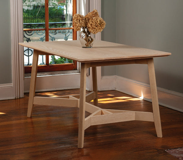
The classic hayrake table is a large, sturdy, dining table born of the English Arts & Crafts movement. Typically featuring beefy legs and heavy components, the central “hayrake” structure ties the table legs together, while leaving room for chairs and human legs to fit comfortably under the table. The “hayrake” name comes from the way each end of that central structure mimics the appearance of a farmer’s tool used for gathering hay.
I’ve always admired the engineering of these hayrake structures, and I wanted to employ their elegant design inside a lighter-weight table for a modern household. My version features splayed legs and thinner components than its predecessors, while still enjoying the strength provided by the triangulated structure. The 3 × 5' tabletop will seat four comfortably, or six cozily, but the base could easily support a larger tabletop if you’re planning a bigger Thanksgiving feast.
A petite table with two key angles
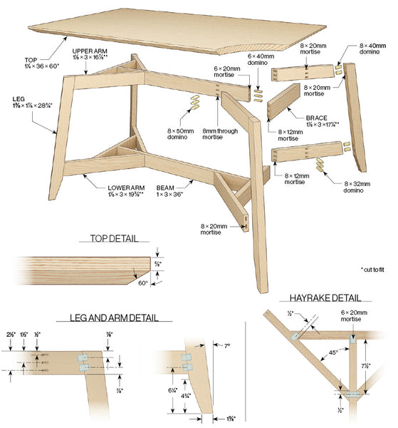
This ash table breaks down into a few simple, repeating components. Two beams stretch down the center of the understructure, at typical apron and stretcher heights. Toward the end of each beam, arms attach at 45° via floating tenons that mortise into their ends, passing through the beam in between. The upper arms sit directly above the lower arms and each upper/lower pair connects to a single, 7° splayed leg with more floating tenon joints. Each arm-to-beam joint is reinforced by a brace that connects both arms and the end of the beam, completing the hayrake structure. I attached the tabletop with figure-8 fasteners for their simplicity and low profile.
Begin with the arms and legs
Mill stock for the legs and all the hayrake parts. Rip all parts of equal width at the same time. Cut the beams to final length but leave all other parts 3" overlong. Set your miter saw table angle to 7° and saw legs to length. Without changing the angle setting, saw one end of each hayrake arm. Lay out and cut mortises in the legs and angled ends of the arms as shown. Dry fit each arm to its respective leg and place one assembly onto the hayrake crosscut jig (see drawing below), registering the inside corner of the top arm-leg joint with the upper corner of the forward crosscut support. Tilt your table saw blade to 45° and slide the crosscut jig to saw both arms to length in one pass. Repeat with a second arm-leg assembly. To make the other two assemblies mirror the first two, flip them end-for-end, and register the inside corner of the top arm-leg joint to the lower corner of the rear crosscut support as shown before sawing arms to length. Disassemble and taper the end of each leg with a tapering jig at the table saw.

Domino the legs. Adjust the height of the Domino’s fence such that it centers the bit on the thickness of the legs. With an 8mm bit, plunge 20mm deep at each mortise location. Without changing any Domino settings, bandsaw a notch into a 1⁄8" spacer and place it on top of each arm before cutting the matching mortises.


Registration is key. For two of the arm-leg assemblies, register the arms in front of the crosscut supports, aligning the inner corner of the upper arm joint with the upper corner of the forward support. For the other two, register the arms behind the crosscut supports and align the upper arm joint with the lower corner of the rear support.

Taper the feet. Place one leg in a tapering jig with the mortises facing the table saw blade. Saw the taper and repeat on the other three legs.
Build the hayrakes
Lay out the mortise locations on the beams and the freshly sawn ends of the arms, marking the centerline on the top edge of each and down the face into which the mortises will be cut. For speed and consistency, add spacers under the Domino machine as you cut the three mortises at each joint, with an 8mm bit. Dry fit the arms to the beams, and cut the braces to fit as shown. Lay out the mortise locations for the brace joinery on the brace, arms, and the end of the beam. Employing the same spacer system that was used to cut the arm-to-beam joints, cut the arm-to-brace mortises with an 8mm bit, and the brace-to-beam mortises with a 6mm bit.

Mortise through the beam. Attach a sacrificial board to the beam face opposite your layout lines. Adjust the Domino’s depth setting to 28mm before placing the tool onto a 1⁄8"-thick spacer and cutting a mortise all the way through the beam. Add a 1"-thick spacer and plunge the second mortise. Add another 1"-inch-thick spacer before cutting the final mortise.

Mortise the arms. Adjust the Domino’s depth setting to 12mm before using the same spacer system to cut the mortises in the beveled end of each arm.