Utility and mobility in one neat package
Designer: Craig Bentzley
Overall dimensions: 96"w × 48"d × 72 1⁄4"h
One of the best ways to gain space in a woodshop is by having your workstations do more. This shop fixture makes the most of that concept by combining a mitersaw station, lumber rack, and tool storage all into one neat mobile unit.
Creating a multi-use workstation often demands compromise, but not here. The mitersaw station component is fully fleshed out with long auxiliary support tables for easy stock handling. The flip-stops on the fence allow convenient, accurate cutting of multiples, with the left-hand table including an extension with a flip-stop for cutting boards up to 78" long. The saw and tables sit atop a row of spacious storage cabinets that includes drawers and a tilt-out bin for offcuts. Two overhead cabinets with adjustable dividers provide easy access to drills, power nailers, and other commonly used tools.
The lumber rack on the back side can accommodate hundreds of board feet of stock, keeping it organized and accessible for easy retrieval. The rack includes a center pocket for housing sheet goods, which can otherwise be a challenge to store.
Note: The key component of this two-sided station is Bosch’s new GCM12SD 12" dual-bevel mitersaw.

Unlike standard sliding compound mitersaws (SCM), the Bosch’s axial glide system allows the tool to make wide cuts without the need for a lot of extra space at the rear of the saw to accommodate the rails.
This station will also work with standard mitersaws, but you may need to adjust the height of the auxiliary tables. For standard SCMs, attach a wide top to the cabinets to accommodate the throw of the rails at the rear.

 Build the Platform
Make the frame
1 Lay the platform bottom (A) on a flat work surface. The stacking stools shown on page 36 work well for the job.
2 Dress the poplar frame parts (B, C, D, E) to the sizes shown in the Cut List. To ensure a flat finished platform, make sure to joint one straight edge on each piece before ripping it to width. Make the caster support blocks (F) at the same time.
3 Lay out the frame parts on the platform bottom as shown in Figure 2. Attach them with 3" screws, pulling the parts together as necessary using clamps, as shown in Photo A.
4 Glue and screw the caster support blocks (F) in place.
5 Plane or belt-sand any high spots on the frame to create a flat plane for the platform top (A).


Attach the top and bottom
1 Lay the platform top (A) atop the frame, centering it to create a consistent overhang all around.
2 Mark out the frame piece centerlines on the panel; then lay out the screw locations, spacing them about 12" apart while avoiding the screws in the frame.
3 Clamp the top (A) to the frame and drill countersunk pilot holes for 1 1⁄4" PowerHead screws. (If your screws are threaded within 1⁄2" of the head, also drill clearance holes to ensure that the screws pull the top tightly to the frame.)
4 Remove the top (A) and apply construction adhesive to the upper edges of all the frame members, as shown in Photo B.
5 Replace the top (A), again carefully centering it on the frame. (A helper can be useful for this step.) Screw the top to the framework, using 1 1⁄4"-long screws (Photo C).
6 Rout the upper edges of the panel with a 1⁄8" round-over bit to remove sharp corners.
7 Flip the assembly over (setting the unattached bottom panel (A) aside for the moment), and plane or belt-sand any projecting areas of the frame to create a flat plane for the bottom panel.
8 Place the bottom panel (A) atop the frame, and mark it for screw locations as before.
9 Viewing across the plane of the bottom end to end, sight the platform for twist. Shim corners if necessary to create a flat assembly. This is important to do before drilling for the screws, as you will otherwise lock any twist into the assembly, thwarting a flat finished platform.
10 Drill countersunk pilot holes (and clearance holes if necessary) as before.
11 Apply a bead of construction adhesive to the frame edges, and then screw the bottom (A) to the framework.
Attach the casters
1 Using a caster mounting plate as a template, lay out the holes for the lag screws. Orient the mounting plates so their length parallels the length of the caster support blocks (F). Shift the plate layout at the corners to avoid the screws at the frame corner joints.
2 Drill pilot holes for 1⁄4 × 1 1⁄2"-long lag screws, making sure you bite into the frame and caster blocks. Also drill clearance holes to accommodate the unthreaded section of the lags.
3 Attach the casters using lag screws and washers.
Build the Lumber Rack
Make the parts
1 Using poplar, cut the posts (G) to the sizes shown in the Cut List. Note: Resist the temptation to use construction 2×4s instead, as they’re prone to warp and their faces are often not flat enough to provide good contact with the arms, which may compromise strength.
2 Using 3⁄4" plywood, cut the blanks for the arms (H) to the size shown in the Cut List. (The 3 7⁄8" width maximizes use of a full-width panel section, but this is actually a good opportunity to use up scraps.) Also saw the feet (I) to the size shown.
3 From solid wood, rip the foot cleats (J) to the sizes shown in the Cut List.
4 Saw the end panels (K) and side panel (L) to the sizes shown, except leave the side panel a couple of inches oversized in length for now.
5 Cut the arms (H) to the shape shown in Figure 3. For efficiency, you can stack-saw them at the bandsaw, taping four blanks together for cutting at once.


Build the post-and-arm assemblies
1 Glue and screw a cleat (J) to each foot (I), where shown in Figure 3.
2 Glue and screw a foot (I) to each post (G), using six screws. Ensure that the foot is square to the post and flush to its bottom edge, drive in two screws, and then check for square as shown in Photo D before installing the remaining four screws.
3 Glue and screw the arms (H) to each post. For quick, accurate alignment, use a spacer board and square, as shown in Photo E.
4 Complete each post-and-arm assembly by adding the second post (G), connecting it with an end panel (K) glued and screwed in place. Also attach with screws (but no glue) a temporary spacer near the bottom end to stabilize the assembly for installation. Everything can be quickly and easily squared up by working on the platform, registering the parts against alignment blocks screwed to the platform, as shown in Photo F.


Install the rack
1 Stand a posts-and-arms assembly (G, H, I, J, K) on the platform, centering the foot cleat (J) over a platform rib, where shown in Figure 2. Then screw the cleat to the rib using 2"-long screws. Make sure that the foot is square to the platform, with its toe aligned with the platform edge. Repeat for the three remaining assemblies.
2 With the posts-and-arms assemblies installed, measure for the finished length of the side panel (L), and crosscut it to size.
3 Screw the side panel (L) to the tops of the posts (G), as shown in Photo G, making sure that the posts are square to the platform. (If you suspect you may have to move this station someday, don’t attach the panel with glue.)
Build the Cabinets
Make the cases
1 Cut the base cabinet sides (M), tops and bottoms (N), backs (O), and shelves (P) to the sizes shown in the Cut List. At the same time, make the equivalent parts (Q, R, S, T) for the upper cabinets.
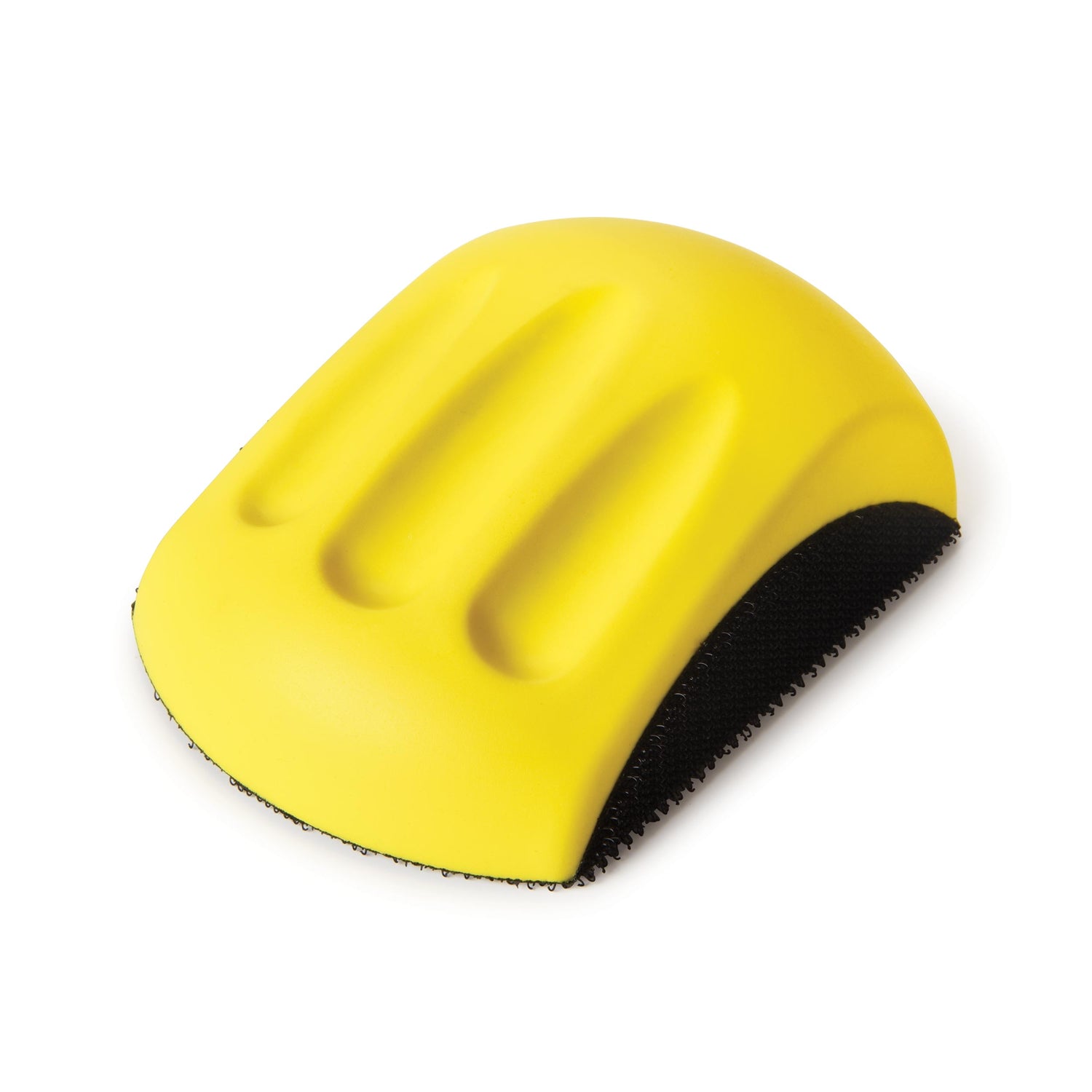
2 Use a household iron to apply veneer tape to the front edges of the sides (M, Q), tops and bottoms (N, R), and shelves (P). Then carefully sand away any tape overhang, pushing your sanding block inward only to avoid pulling the tape off.
3 Saw or rout the rabbets on the ends and rear edges of the sides (M, Q), where shown in Figure 4.
4 Cut the upper cabinet dividers (T) to the size shown in the Cut List. Then saw the kerfs for them in the tops and bottoms of the upper cabinets (R), where shown in Figure 4.
5 Glue and nail the tops and bottoms (N, R) to the sides (M, Q). Then glue and nail the backs (O, S) into their rabbets, taking care to keep the cases square.


Install the base cabinets and hardware
1 Place the cabinets on the platform in the configuration shown in Figure 1. Clamp adjacent cabinets together with their front edges flush, and screw them together at the fronts, as shown in Photo H, and at the rear. Where possible, drill a few screws through the cabinet bases and backs into the platform ribs and lumber rack posts, making sure the posts are square to the platform.
2 Drill for the shelf-pin holes in the outermost cabinets using a 1⁄4"-diameter bit, as shown in Photo I. Then insert the shelf support pins and install the shelves.
3 Attach the drawer slides, referring to Figure 5 for the proper spacing. The easiest and most accurate approach is to use a carefully squared plywood panel as a support spacer, as shown in Photo J. Begin with a 23 3⁄4"-long panel, using it to register the topmost slides. After attaching them, cut the panel to 19 5⁄8" to install the next slides down, and so on.
Build and install the drawers
1 Make the drawer sides (U), fronts and backs (V), and bottoms (W) to the sizes shown in the Cut List.
2 Saw the rabbets and grooves in the parts, where shown in Figure 6.
3 Assemble the drawer boxes, gluing and nailing the sides to the fronts and backs, and gluing the bottoms in their grooves. To ensure proper operation, make sure the boxes are dead square and flat.
4 Attach the drawer halves of the slide sets to the drawers, and then mount the drawers in the case.
5 Saw the drawer false fronts (X) to the sizes shown in the Cut List. Apply veneer tape to the edges, and then sand the edges of the tape flush as before.
6 With the drawers in the case, screw on the false fronts through holes drilled in the box fronts, where shown in Figure 6. Attach the bottom drawer first; then place 1⁄8" shims on its top edge to serve as spacers for attaching the drawer front above. Repeat for the remaining drawers.
7 Drill for the drawer pulls and install them.

Drill shelf pin holes using pegboard or a commercial guide like the WoodRiver model shown here.

Support the slides for installation with a spacer panel, cutting it shorter as you progress downward.
Install the upper cabinets
1 From 1⁄2"-thick plywood, make the backboard (Y) to the size shown in the Cut List. Rest it on the top edges of the base cabinets and screw it to the lumber rack posts.
2 Screw the upper cabinets through the backboard into the posts, as shown in Photo L, using 1 1⁄4" and 3" PowerHead screws. (Note: To support heavy loads, consider adding a brace behind the left-hand edge of the upper right cabinet.)
3 Install the 1⁄8"-thick hardboard dividers (T) into the cabinets.


Make the auxiliary tables
1 Saw the tops (Z), bottoms (AA), fronts and backs (BB), and fences (CC) for the auxiliary tables to the sizes shown in the Cut List.
2 Saw or rout the grooves in the tops (Z) and bottoms (AA) where shown in Figure 7, and rabbet the rear edges of the tops.
3 Drill the 1⁄2" holes for lag screws in the bottoms (AA), insetting them 3⁄8" from the edge. The holes are oversized to allow for some fore-and-aft adjustment of the installed tables.
4 Drill a hole in the left-hand riser (BB) to accept a 3⁄8"-16 T-nut for the extension arm lock knob. Counterbore the inside face first to recess the flange; then drill the through hole. Install the T-nut.
5 Miter-cut the innermost corners of the tops (Z), where shown in Figure 7, to accommodate the swing of the saw table.
6 Glue and clamp the tops and bottoms (Z, AA) to the risers (BB). Make certain that the assemblies are square under clamp pressure and that the ends are flush.
7 Clamp the fences (CC) to the extension tables, and then drill pilot holes to attach them. Drill clearance holes through the fences to ensure that the parts pull together completely. Then screw on the fences.


Make the extension arm
1 Make the extension arm sides (DD). Rather than sawing them to the exact width shown in the Cut List, fit them to the actual inside height of your left-hand extension table. Test the ripped pieces to make sure they slide easily within the table cavity, but without slop.
2 Saw or rout the grooves in the sides (DD), where shown in Figure 7. Then, with the sides in place in the extension table, measure across from groove to groove to determine the exact width of the top and bottom (EE). After cutting the top and bottom to size, dry-assemble the extension arm and check the fit in the table cavity. Again, it should slide easily with no slop. When it fits well, glue and clamp the arm together.
3 Slip the 6"-long auxiliary table extension assembly over the extension arm, and join the pieces together with glue.

Mount the saw and auxiliary tables
1 Install the saw. (Note: I set the saw on top of a 3⁄4" MDF pad in order to widen the risers (BB) used on the auxiliary tables.)
2 Use a straightedge held against the saw fence to align the auxiliary tables, as shown in Photo L. Then attach the tables to the cabinets using 1 1⁄2"-long × 1⁄4" lag screws with washers.
3 Insert the extension arm and install its lock knob.

Make the offcut bin
1 Saw the false front (FF) to the size shown in the Cut List. Cover the edges with veneer tape, and sand any overhang flush.
2 Saw the fronts and backs (GG), sides (HH), and bottom (II) to the sizes shown in the Cut List.
3 Saw the angle on the sides, as shown in Figure 8.
4 Glue and screw the bottom (II) to the sides (HH) using #6 × 1 5⁄8"-long screws.
5 Glue and screw the sides (HH) to the front/back/bottom assembly.
6 Attach the false front (FF) with screws reaching through clearance holes drilled through the box front (GG). Then attach the pull.


