Folding legs and fine joinery make this server special.
Sometimes a small project is just the thing to fill up a little bit of shop time. It’s even better when you get the opportunity to transform some scrap stock into a nice gift or an addition to your home. This serving tray scores well on both counts. Folding legs enable the tray to sit flat on a table or have an elevated stance, as shown above. The tray’s laminate-covered bottom can easily endure spills and hot plates. And despite the small size of this project, it contains some nice joinery challenges: corners made with finger joints, and template-routed handles and curves.
The details ahead show you how to make a single serving tray, but this project lends itself well to making multiples. Once you’ve set up your box joint jig and made the templates, a limited production run is easy to accomplish.
Well-crafted corners, graceful curves, and legs that swing
The tray is sized to fit a common dinner plate, but dimensions can be easily adjusted if you prefer a more spacious tray. Combining maple sides with walnut ends adds some visual drama, but I’ve also built a number of trays with just one wood species.
 Order of Work
- Make templates for tray sides and handle.
- Cut finger joints in sides and ends.
- Rout curves in tray sides, then rout handle openings.
- Rout grooves for tray bottom, and make bottom panel.
- Install threaded inserts, then assemble the tray.
- Make and install the leg assemblies.

Begin your joinery work with the tray’s corners.
I’ve used through dovetails as well as finger joints to join tray sides and ends. In both cases, I rely on commercial jigs to guide my router. The Leigh Box Joint & Beehive Router Jig featured here is sturdy, accurate, and easy to use. The jig has a routing template that contains two guiding “combs”—one for making 3/4"-wide fingers, the other for 1/2"-wide fingers. The smaller size fingers definitely look better in this project, and the 3" width of side and end pieces eliminate unsightly partial fingers. Follow the manufacturer’s instructions to set up your jig. Then set yourself up for success by preparing your stock carefully, including a few extra pieces so you can rout test joints and make any necessary adjustments.

Pins in the ends, sockets in the sides. Routing the tray’s finger joints goes quickly, once you’ve set up the Leigh jig as shown here. The jig’s adjustable guide bushing enables you to get joints just right (fitting snugly but not forced) after a couple of test joints. A stop attached to the shop-made beam automatically aligns the correct offset when switching from routing pins to routing sockets. Prevent tearout when routing pins by clamping a side backer board in place, as shown here.

Use jigs to rout curves and handles.
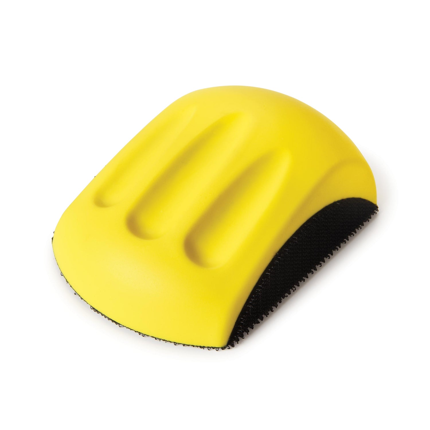
It’s important for the tray’s curved sides and handle cutouts to come out smooth and symmetrical (See patterns, p. 27). To get the results I’m after, I rely on a side routing jig and a handle template that are designed to be used with pattern-routing bits and guide bushings. The key to this approach is make both guides carefully. I cut the tray side pattern on my band saw, then smoothed the pattern with a rasp and sandpaper. To make the template for the handle cutout, I jigsawed just inside the lines, then smoothed the cutout with sandpaper. Wrap your sandpaper around a 1/2" dowel to smooth the curved corners.

Flush-trim with a half-pattern. The jig I use to rout the side cutouts consists of a base that guides the pattern-routing bit, fence pieces that register the side’s bottom edge and ends, and a pair of hold-downs. To prepare each side for this pattern-routing step, rough out the side’s shape by cutting about 1⁄8" outside the line. Then clamp the side in the jig, and let the bearing follow the pattern to cut a little more than half the finished shape. Flip the side and repeat to complete the cutout.

Rout handles with a bushing, then a bearing. The 1⁄4"-thick handle template is the same size as the tray ends. To prepare for routing a handle opening, I clamp the template and end together in the face vise on my workbench (photo at left). Then I rough out the opening with a guide bushing and upcut bit, making successively deeper passes (photo above). Finish the opening using a 1⁄2"-dia. pattern-routing bit.
Prepare the frame for the legs and bottom, then put the tray together.
For durability as well as appearance, I used a tray bottom made by gluing (with contact cement) two sheets of plastic laminate to a 3/16"-thick MDF core. I like to make up a large laminated panel—big enough to yield 3-4 tray bottoms—and then cut these parts to final size.
Instead of routing bottom grooves separately, I prefer the speed and accuracy of clamping the frame together and routing all four frame members at once. Before gluing the tray together, give the interior faces of the sides and ends a final sanding.

Grooves, then inserts. Clamp sides and ends together to mill the groove for the tray bottom. My slot-cutting bit cuts 1⁄8" wide and 3⁄8" deep. Several passes are required to complete the groove for my 5⁄16"-thick, laminate-faced panel. After grooving, disassemble the tray and install threaded inserts for the leg screws.

Curve the corners, then assemble. It’s not necessary to chisel the ends of the bottom grooves square if you round the corners of the bottom panel to match the radius of your slot-cutting bit. I did this rounding with a stationary belt sander. Go through a complete dry-fit assembly to make sure all five parts go together. Then glue only the corner joints, letting the panel float in its grooves. Use 2 pairs of clamps as shown to hold corners tight as the glue dries.
Add leg assemblies that swing out of sight.
All the tray needs now are two leg assemblies that can hide underneath the bottom or swing open when the tray needs an elevated stance. To make the leg assemblies, start by cutting mortises 1-5/8" up from the leg bottoms, and snug-fitting tenons in the rails. Drill a hole in each leg for a mounting screw; center the hole 7/16" from the top of the leg. Before glue-up, round all leg ends. I did this on a stationary belt sander, but you could also rout leg ends with a roundover bit. Although I skipped this step in the photos shown here, it’s smart to sand and finish your leg assemblies before installing them. My finish treatment was three coats of clear shellac.


Shop Tip
To help hold the mounting screws in place, you can use a pair of locking pliers to slightly mar the threads near the tip of each screw. This makes the screw a little harder to drive, but it will stay locked in place.

Nice job! These trays make gifts that keep on giving. As shown here, through-dovetails also look good as corner joints.


