Sling your six-string safely and in style

Buying a guitar leads to owning a plethora of other gear: strings, picks, (a second guitar,) straps, amps, (more guitars,) and of course those ubiquitous collapsible metal stands. They’re great for the road, but at home where I want to keep my nicer six-string close at hand, I thought its stand should—well, stand up—to the guitar. And that meant a quality wooden structure that would safely support the instrument without overshadowing its elegant form and wooden beauty.
Picking up on the sensuous curves and subtle angles of my Martin D-35, I designed this stand with both curved and straight elements joined with binding screws and shiny metal spacers (see Buyers Guide). These spacers make me think of a guitar’s tuning pegs, while the upright is reminiscent of the instrument’s neck. I went with bent lamination to make the curved pieces, sawing thin strips of wood to bend for the shallow curve of the spine and purchasing veneer for the tighter curves of the base and supports. I chose to make my stand from maple because its simple grain doesn’t detract from the spruce and rosewood components of the guitar; but any hardwood will do as long as you can get veneer strips at least 30" long.
Layers and layers of laminations
The U-shaped guitar supports and base are laminated from veneer strips shaped around forms. The spine consists of three 1/8"-thick hardwood laminations, also glued up on a form. The veneer is great for tight bends while the thicker hardwood strips makes the thin spine plenty sturdy. The upright is shaped from solid hardwood and attached to the base with a mortise and tenon joint, while binding screws and metal spacers connect the rest of the parts.

 Order of Work
- Cut laminate and create forms
- Bend and glue laminates on forms
- Trim and shape U-bends
- Drill for hardware
- Create upright support
- Sand and finish
- Assemble
- Rock out!
 onlineEXTRAS
Form patterns and CNC files.
Bending more than strings
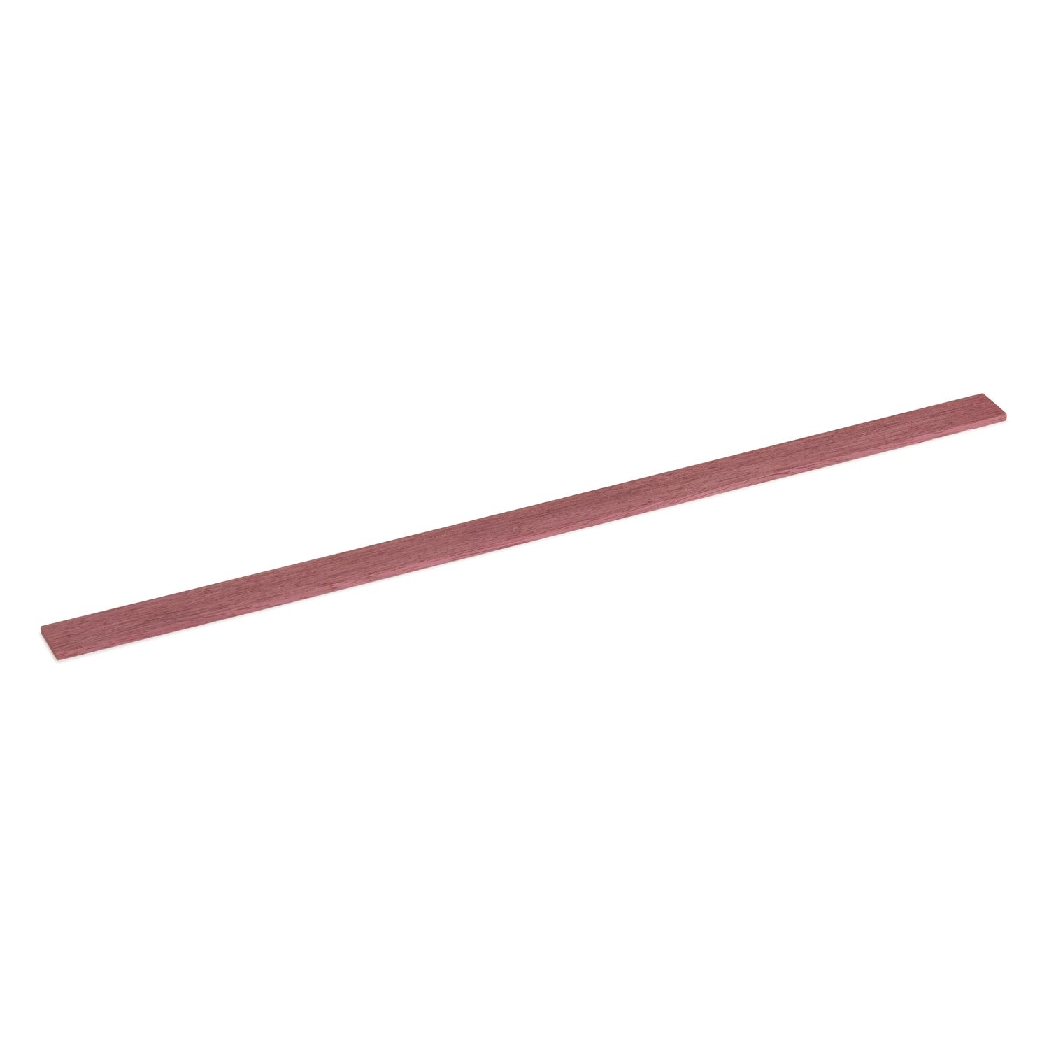
At the table saw, rip three strips measuring 1/8 × 1-1/2 × 33", positioning each cut with a gauge block. Make the spine form from a double layer of 3/4" MDF. Then cut veneer strips at least 1/4" wider than the final width of the base and supports. The veneer strips should be at least 29" long for the base, 20" for the lower support, and 9" for the upper support. I found a hobby knife and straightedge the quickest way to make the cuts. Slice enough veneer layers to create the thickness of the base and each support.
Make the upper support form from two layers of 3/4" MDF, and the base/lower support form (both pieces use the same form) from three layers, screwed—not glued—together. Cut the forms and sand them to final shape (or download the files and have a CNC router cut the forms for you). Glue and clamp the strips around the forms. After bending all four pieces, trim to final width as shown.


Glue up spine. Spread glue on one face of each spine strip, then stack and clamp to the form. Holes in the form ensure the clamps stay perpendicular to its surface, while a few strips of 1⁄4"-thick plywood protect the strips and help evenly distribute the clamp pressure.

Glue up U-shapes. A wide band provides excellent pressure around the curved portion of the form, but add two or three F-clamps and cauls on the straight portions to ensure good pressure here.

Clean up the laminations. For the spine, clean one edge at the jointer, then trim to final width at the table saw. For the U-shapes, remove one layer from each form and adhere the laminations to the form with double-faced tape. At the router table, trim the pieces to match thickness of the forms with a flush trim bit.
Setting the stage
Bore holes in the spine to accept the hardware that will attach the guitar supports. Then round over the edges of the base and supports at the router table before bandsawing each veneer U-shape to length. Back at the drill press, secure each support in a wooden handscrew clamp as shown, making sure both ends are equidistant above the drill press table. Then bore a series of concentric holes, creating relief for the head and shaft of the nut.

This is Spinal Tap. At the drill press, align the centerpoint of the spine form under a 1⁄4"-dia. bit and clamp the form in place. Bore two holes though the spine, centered on its width and located 11⁄2" from each end.

Rounding the bends. Soften the edges of the U-bends at the router table. Give the upper support a 1⁄8"-radius roundover, switching to a 1⁄4"-radius bit for the base and lower support.

Counterbore the supports. Hold the workpiece with a handscrew clamp and bore an 11⁄16"-dia. hole 1⁄8" deep in the center of the concave side of each support. Using the same centerpoint, drill a 3⁄8"-dia. hole 1⁄2" deep, then finish boring through the U-bend with a 1⁄4" bit.
 Upright base
Cut the mortise for the upright at the apex of the base’s curvature. Lay out the upright’s profile (see the drawing at right) on straight-grained, milled stock. Saw and sand to shape. At the bottom of the upright, create a tenon at the router table by rabbeting both sides of the workpiece. I found it was easier to round the tenon’s corners with a file than to square the mortise in the laminated veneer. To drill the holes for the bolts that will connect to the upright to the spine, place the angled section face-down on the drill press table and bore through from the back. Start with a 3/8"-dia. hole, 1/2" deep, then finish with a 1/4"-dia. through-hole. Clamp the upright and spine together with the spacers in between. Align the pieces with help from a square and 1/8"-thick spacer as shown. Then drill 1/4"-dia. holes through the spine. Glue the upright and base together. Add a slight countersink to the head side of every bolt hole for the small fillet under the bolt’s head, allowing the head to seat firmly against the wood. Radius the ends of each laminated part for aesthetics and to safeguard your guitar. Predrill screw holes for the rubber bumpers on the lower support. Then sand and finish the pieces before assembling—I used water-based polyurethane that wouldn’t yellow the maple.

Mortise the base. Clamp the base onto its form and mark the apex for a 1"-long, 1⁄4"-wide mortise. Screw a fence to the form parallel to the mortise layout. Cut the 1" deep mortise in several shallow passes with a 1⁄4" straight bit in a plunge router.

Drill for the barrel bolts. With the bottom 31⁄2" of the upright clamped in a bench vise, adhere spacers to the angled section with double-faced tape, locating them with bolts pushed through the upright. Clamp the spine in place with its lower end touching the bench, then drill through it using the existing holes and spacers as a guide.

Glue the upright. Grip the upright with a handscrew clamp to create a clamping surface for putting downward pressure on the upright. After clamping the joint together, squeeze the base with a C-clamp (and cauls) to ensure good cheek-to-cheek glue contact inside the joint.
Buyer's Guide
- Sauers Maple Wood Veneer Pack, 12 sq. ft. — #131446, $21.99
- WoodRiver 11⁄16" High-Carbon Steel Forstner Bit — #125930, $10.99
- Pony 10 ft. Band Clamp — lowes.com, #4131486, $39.98
Following available from mcmaster.com:


