Paving the way to playtime adventure
Overall Dimensions: 9"w × 18 1⁄8"l × 7 3⁄8"h
Add to your tough-enough toy collection with this rugged grader. The wheels pivot and the blade rotates, allowing young tykes to create their own perfect sandbox roadways and construction sites. Discover a safe and effective way to make off-road tires for gripping the rough terrain.

Ordering the truck and front-end loader plans
For the full-sized patterns of the front-end loader, and to “kick the tires” on the rest of the Tough-Enough Truck fleet (plans available for purchase), see onlineEXTRAS.


Start with the frame
1. Cut and laminate two pieces of 3⁄4"-thick maple face to face to form a blank for the frame (A) for a finished size of 1 1⁄2 × 2 1⁄8 × 17". (See Figures 1, 2, and 3 for reference.) Lay out the opening in the blank as dimensioned in Figure 2 and cut the frame profile to shape. (Use a dado blade and tablesaw to create the square-cornered notches and a bandsaw to complete the cuts.)
2. Cut the blade pivot (B), axle support (C), and front (D) to the sizes in the Cut List from maple. Drill countersunk mounting holes and screw (A) to (B).
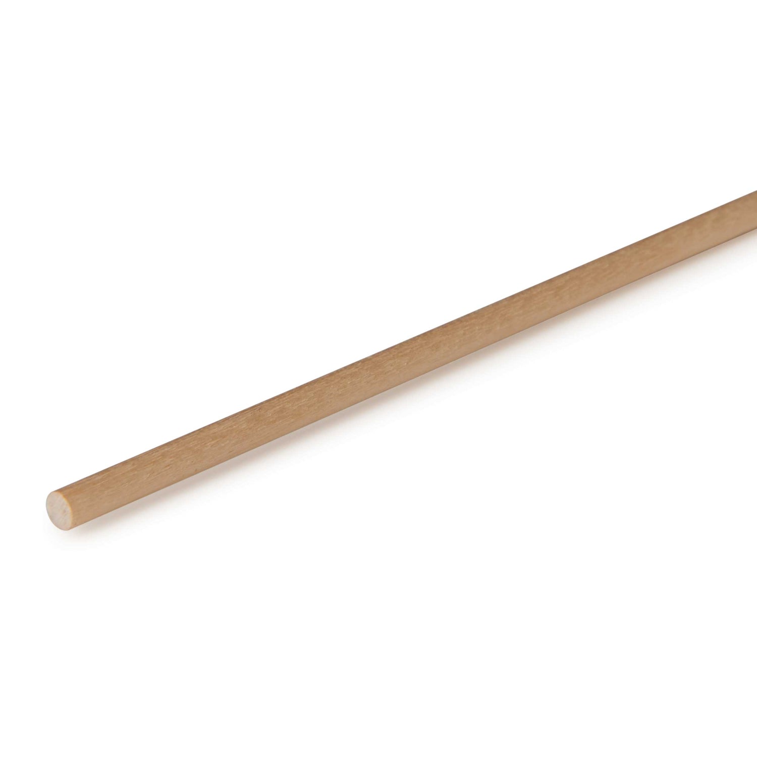
3. Drill the 11⁄32" holes in (C) and (D). Using an 11⁄32 × 2 9⁄16" axle peg inserted through (D) and into (C) to maintain alignment between the two holes, glue and screw these parts to the frame (A). Cut the frame top (E) to size from walnut and glue it to the frame (A).
4. Mark the centerpoint, and then drill the 1⁄2" blade pivot hole through the assembled frame parts (A), (B), and (E). If your bit is not long enough to bore through, flip the assembly bottom edge up and complete the centered hole, as shown in Photo A.
5. Lay out the cutline on the side of frame parts (D) and (E), where dimensioned in Figure 2. Bandsaw the frame’s top edge to shape, as shown in Photo B. Sand the sawn edge smooth.
6. Cut the rear frame bottom (F) to size, as shown in Figure 3.
Lay out and cut the 11⁄2" dado, 1⁄8" deep, across the piece on the top surface. Cut a 1" dado, 1⁄8" deep, for the rear axle (R) on the bottom. Drill the screw mounting holes. Screw the part to the frame assembly, where shown in Figure 2, aligning the back edge with the 1⁄8" notch.


 Add the cab
1. To form the cab side windows (G), cut a piece of 3⁄4" stock to 2 3⁄4" wide by 8" long. Cut a 1⁄4" groove, 1⁄4" deep, where shown in Figure 4. Cut a window divider (H) to fit into the groove, and glue it in place. Crosscut two G/H assemblies to 3" long from the blank.
2. Cut the cab side bottoms (I) to size, and glue one to each side assembly (G, H) with the edges flush, creating a “left” and a “right” cab side by positioning the parts, as shown in Figure 4.
3. Using a dado set, miter gauge, and an auxiliary fence for support, cut a 3⁄4" rabbet 1⁄2" deep along the bottom end on the inside face of each side assembly (G/H/I). Cut the cab sides to the finished length of 5".
4. For the cab front and backs, cut the cab end windows (J) and cab end bottoms (K) to size, plus 1⁄2" in width and 2" in length. The extra length is needed for safely cutting the rabbets in Step 5. Glue the pieces end to end. Trim the edges flush for a finished width of 3".
5. Using a dado set at the saw table and a pushblock, cut a 1⁄2" rabbet 1⁄2" deep along both inside edges of each cab side assembly (J/K).
6. Trim the (J) part of the assembly (J/K) to 1 1⁄2" long. Then, crosscut the overall assembly length to 4 1⁄4". Lay out the notches in the cab end bottoms (K) to slip over the frame (A). Bandsaw and sand the parts to shape.
7. Dry-fit the cab sides to the front and back. There should be a 1⁄4 × 1⁄4" rabbet along each corner. Also check that the cab assembly fits snugly over the frame (A) and frame bottom (F). Glue and clamp the cab assembly together keeping the top and bottom ends flush.
8. To form the rounded-over cab corner (L), cut a piece of 3⁄4" walnut to 2" wide by 11" long. Rout a 1⁄4" round-over along two edges of the blank.
At your tablesaw, rip two corner pieces for (L) from the blank. Crosscut four cab corners to length, and then glue them in place, as shown Photo C.
9. Drill the mounting holes, and screw the cab assembly to the frame (A), as shown in Photo D.
10. Cut the cab top (M) to size. Rout a 1⁄8" round-over on all edges. Drill a pair of 11⁄32" holes for the lights in the front and back edges. Finish-sand the cab and add the lights. Set the top aside; we’ll add it later.

Assemble the motor
1. Cut the motor’s grill (N), sides (O), and top (P) to size, as shown in Figure 5 and noted on the Cut List.
2. To cut the grill kerfs, install a zero-clearance insert in your tablesaw, and raise the blade 1⁄8" above the table. Lay out the kerf locations shown on Figure 5, keeping in mind you’ll trim the top end of the grill when bandsawing the motor top to shape in Step 3 at right. Cut the kerfs in the grill.
3. Dry-clamp the motor assembly (N, O, P) and test-fit it on the frame. Adjust if necessary; then glue and clamp the motor assembly together. Mark the tapered cutline and bandsaw the top rear of the motor to shape. Glue and screw the motor to the frame and cab.
4. Mark the cutline, and cut the bottom front corners of the cab flush with the tapered front edge of the frame (A), as shown in Photo E. Sand smooth.


With the workpiece held vertically to the fence, drill into both ends of the axle supports for the axle pegs.
Add the axle supports
1. Cut the front and rear axle supports (Q, R) to size from 3⁄4" stock. Bevel-cut or sand the bottom edges at 45°. Secure the pieces to the fence with stops, and drill 11⁄32" axle holes in each support to the depth shown in Figure 1 and in Photo F.
2. Use an axle peg to pin the front axle support (Q) to the frame assembly. Glue and screw the rear support (R) to the bottom of the frame bottom (F).
3. Cut the rear wheel pivots (S) to size. Mark the three centered 11⁄32" peg holes and 1⁄2" radii, where shown in Figure 3. Drill the peg holes, and then cut and sand the radii to shape. Add the finish to the rear wheel pivots, and set aside to add later.


Make and install the tires
1. To make the 3"-diameter tire halves for the six grader tires (T), extra halves for testing setups, and the two kerfing templates, lay out eight centerpoints on each of two 1⁄2 × 4 × 28" maple blanks.
2. Insert a 3⁄8" brad-point bit in your drill press, adjust the fence to center the bit on the centerpoints, and drill 1⁄4"-deep starter holes at seven centerpoints in one of the maple blanks. These will become the outside faces of the inside tire halves. Switch to a 11⁄2" Forstner bit, and bore a 1⁄4"-deep recess at seven centerpoints in the other maple blank. These will become the outside faces of the outside tire halves.
3. Next, switch to a circle cutter adjusted to make a 3"-diameter cut. (Orient the cutter’s bevel to face away from the center; the point of the cutter should be on the inside). Adjust the fence on your drill press, and clamp a maple blank to the fence. Then, using a slow speed for safety (about 300 rpm), cut through the centerpoints of each maple blank, as shown in Photo G, creating 16 discs. As you cut, you will be drilling a centered 1⁄4" axle hole at the same time. The two discs that were not predrilled will be used for the kerfing templates for kerfing the tire halves.
4. Install a 1⁄8" round-over bit in the router table. Then make a simple L-jig out of 3⁄4" scrap, drilling a 1" hole in the jig’s inside corner. Secure the jig to the table with double-faced tape, locating the bearing at the jig’s inside corner. With the 14 tire halves and test pieces placed outside face down, round over the outside edges, rotating them as shown in Photo H.


With the miter gauge adjusted to 60° in the opposite direction of Photo J, dado-cut the treads in the tire halves.
5. Make and then clamp the drilling jig in Figure 6 to the drill-press table and drill a 1⁄4" hole where shown. Insert a 1⁄4"-diameter dowel in the hole to act as a centering pin.
6. Chuck a 3⁄16" bit into the drill press and reposition the jig so the 3⁄16" bit is 1" from the center of the centering pin. Position a tire half on the centering pin with the rounded outside edge down, and drill a 3⁄16"-deep hole. Repeat for all tire halves and the two kerfing templates.
7. Divide the 12 tire halves into two groups: one for the left tire halves and one for the right tire halves. Each group will have three tire halves with the 1 1⁄2" recess cut in them and three without. Mark and keep the tire halves in separate groups to avoid confusion.
8. Next, make two copies of the Kerfing Pattern shown in Figure 6. Cut out the patterns, and glue one to the face of each kerfing template, making sure the kerfing pattern is on the face opposite the 3⁄16" hole. Highlight two adjacent lines on the paper kerfing pattern indicating a starting and stopping point for cutting the kerfs in the kerfing template. Insert a 3⁄16" dowel 3⁄8" long into both kerfing templates in the hole on the back side.
9. Make the kerf-cutting jig shown in Figure 6. Mark an alignment line on the front face, and drill a 1⁄4" hole through the line. Insert a 1⁄4"-diameter dowel 1" long into the 1⁄4" hole. Install a 1⁄4" dado set, and raise it to cut 3⁄16" deep. Adjust the miter gauge to 60° to the right for the first group of wheel halves. Screw an auxiliary extension to your miter gauge. Clamp the Kerf-Cutting Jig to the miter-gauge extension, adjusting the jig so the left side of the dado blade aligns with the alignment line.
10. Place one of the kerfing templates on the jig’s 1⁄4" dowel. Position a test tire half with the alignment pin of the kerfing template engaged into the 3⁄16" hole on the tire half. Align one of the highlighted lines on the paper pattern with the alignment line on the Kerf-Cutting Jig as shown in Photo I. Use a small clamp to hold the two pieces to the miter-gauge extension. Turn on the saw and cut the tire tread. Repeat by rotating and aligning the kerfing template lines and tire half for each kerf cut, making the final cut at the other highlighted line. Check the tread. The kerfs should be evenly spaced.
11. Finish cutting the first tire group, as shown in Photo J. To do this, remove the tire half (but not the kerfing template), and repeat the kerf cutting process with the remaining first group tire halves.
12. Remove the Kerf-Cutting Jig from the miter-gauge extension. Reposition the miter gauge to 60° in the opposite direction, as shown in Photo K.
Clamp the Kerf-Cutting Jig to the miter-gauge extension, adjusting the jig so the right side of the dado blade aligns with the alignment line. Position the other kerfing template, as described in Step 9.
Make the tread cuts, repeating the process with the tire halves from the second group.


13. To bond the tire halves together, select one with the 11⁄2" recess from the first group and glue it to a non-recessed tire from the other group. To eliminate squeeze-out on the treads, spread glue sparingly on the inside (unrounded) faces. Next, insert a 1⁄4 × 3" bolt through a washer, the hole in the tires halves, a second washer, and tighten the halves together with a nut, as shown in Photo L.
(Doing this keeps the halves flush.) As you tighten, adjust the halves to create an offset V-tread pattern. Similarly, glue and clamp the remaining tire halves, resulting in three left-hand and three right-hand tires.
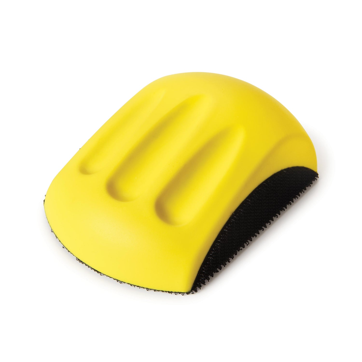
14. After the glue dries, install the bolt of a tire assembly into the drill-press chuck. Turn on the drill press and sand away any burn marks on a tire (T), using a sanding block with 80-grit sandpaper. Finish-sand to 220 grit. Repeat for the remaining five tires.
15. Install a 3⁄8" brad-point bit in the drill press. Using the tool’s fence and a stopblock, clamp the tire to the fence, inserting the drill bit into the tire’s 3⁄8" “starter” hole. Redrill the hole so an axle peg can slip through it. Repeat for the remaining tires, and apply the finish.
Create the adjustable blade assembly
1. Referring to Figures 2 and 3, lay out the turret (U) shape and hole centerpoints. Drill the 5⁄16" and 1⁄2" holes. Cut the turret to shape.
2. From 7⁄16" dowel stock, crosscut the blade rotation pin to 43⁄4" long. Glue the rotation pin to the turret.
3. Cut the blade (V) and blade support (W) to size. These will be added later.
4. Bandsaw or scrollsaw the rotation knob (X) to shape, and drill a centered 7⁄16" hole 1⁄2" deep on its bottom side. Then, drill an 11⁄64" shank hole centered inside the 7⁄16" hole. Glue the turret (U) to the pin. Slide the pin through the 1⁄2" hole in the frame.
5. Cut a pair of turret stops (Y) to shape. Drill a 1⁄4" hole 1⁄2" deep in each. Then drill the screw shank holes, where shown on Figure 3.
The screw shank holes in the turret stops are slightly oversized to allow the turret stops to be adjusted over the holes in the turret. Inset a locking pin (1⁄4" dowel 3⁄4" long) into the hole in each turret stop. Cut the stretcher (Z) to shape. Position and clamp the turret stops against the frame assembly by inserting the locking pins into the center outside holes of the turret (U), as shown in Photo M. Using the holes in the turret stops as guides, drill 7⁄64" pilot holes into the frame for the two screws. Screw the turret stops to the frame, as shown in the photo so that they can move freely.
6. Center and glue the stretcher (Z) to the two turret stops. Center and glue the blade (V) and blade support (W) to the turret (U). Glue and screw the knob (X) on the top end of the rotation pin.
Complete the assembly and add the finish
1. Glue and clamp the cab top (M) to the cab assembly. Add the lights to the front of the frame assembly.
2. Finish-sand all the parts and assemblies to 220 grit. Wipe clean, and apply finish to the assemblies and unassembled parts. (Tom used Watco Satin Lacquer.) Apply finish to just the exposed ends (not the shanks) of the axle parts. Let the finish dry.
3. Orient the left and right tires (T) so the recessed faces are on the outside, as shown in Figure 1.
Place a small amount of glue in the axle peg holes, and then push the axle pegs through the front tires, a nylon washer, and into the front axle support (Q), leaving a clearance equal to the thickness of a business card for the tires to turn freely.
4. Attach the rear tires (T) to the rear wheel pivots (S) with axle pegs through nylon washers. Flush-trim the axle pegs after attaching to the rear wheel pivots. Attach the rear wheel pivots to the rear axle support (R) with axle pegs through nylon washers.
About Our Designer/Builder
Urbandale, Iowa, resident Tom Whalley has been a woodworker for over 40 years and is the current president of the Des Moines Woodworker’s Association. His award-winning designs have been featured in several national woodworking publications. Creating unique “one-of-a kind” projects is Tom’s focus.


