Scoop a bucket-load with this hands-on construction toy.
Overall Dimensions: 6"w × 17"l × 8"h
Designed to go with the Tough-Enough Toy Truck from the February/March 2013 issue, this walnut and maple front-end loader features a lift handle for operating the bucket and depositing sawdust, dirt, sand, or gravel into the truck’s dump box, as well as a pivoting front end. Here, you’ll use the patterns to speed the building time and learn a few tricks for safely cutting small parts. You’ll also find out how to make the rugged V-tread tires at the drill press and tablesaw.
Ordering the Dump Truck Plan
To purchase the Tough-Enough Dump Truck either as a download or an enlarged paper plan, click here.

Tip Alert
First, make the frames
1 From 3⁄4ʺ-thick walnut, cut the rear frame (A) and front frame (B) to the sizes in the Cut List. Then mark the 1 3⁄8ʺ-radius center point which will be used later to bore the centered pivot hole. With your compass draw the radius line on each part. From the radiused end, mark the half-lap shoulder line at 2 13⁄16ʺ. (See the frame parts in Figure 1.)
2 Lay out the rabbet cuts on the frame parts (A, B) using a marking gauge. Set your tablesaw blade height to cut 13⁄32ʺ deep, and then crosscut each part where marked on the bottom face of rear frame (A) and top face of front frame (B). Note that a 1⁄16ʺ–thick fender washer fits between the two frame rabbets, making up the difference in the pivoting half-lap joint, as shown in Figure 1.

3 Set up your drill press with a fence and bore the 7⁄64ʺ pivot hole in rear frame (A) and 5⁄32ʺ pivot hole in front frame (B), where shown.
4 Bandsaw to the marked radius line on the rear and front frames (A, B). Then sand to the line, removing saw marks.
5 Set up your router table with a 1⁄8ʺ round-over bit, and rout the edges of the rear and front frames (A, B).
6 Set up your bandsaw fence and to make a 13⁄32ʺ-deep rabbet cut on each frame (A, B), as shown in Photo A. Sand the sawn surfaces smooth with a sanding block, and test the rabbet-to-rabbet fit, slipping a fender washer in between the parts. The surfaces should be flush.
7 On the side edges of the frames (A, B), lay out the axle peg holes where dimensioned in Figure 1. Set up your drill press with a fence and stop, and bore the 11⁄32ʺ holes. Then drill and countersink all shank holes where shown.


Add the cab
1 Edge-glue a 3⁄4 × 17⁄8ʺ piece of maple to a 3⁄4 × 3 1⁄8ʺ piece of walnut to make a 5ʺ-wide by 20ʺ-long blank for the cab front/back (C) and cab sides (D). See Figure 3: Cab Exploded View. Remove the squeeze-out and let dry.
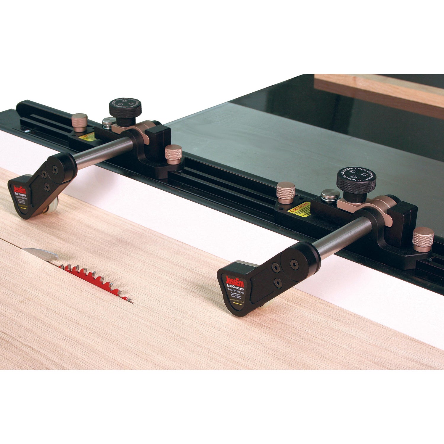
2 Miter-cut the cab front/back (C) pieces and the cab sides (D) to the lengths in the Cut List, following the blank cutting sequence in Figure 2. To do this, install a zero-clearance insert and attach an extension fence to your saw’s miter gauge, placing it in the left-hand slot. (The blade in my saw tilts to the left. Make the needed changes if your saw tilts to the right.) Angle the blade at 45°. Place the cab blank against the extension fence, and miter-cut one end. Measure in 2 3⁄4ʺ from the toe, and lay out the opposing miter-cut for the cab sides on the edges. Flip the blank to place its opposite edge (edge B) against the extension fence, and align the cutline with the blade. Mark the fence with a pencil line or piece of tape to the needed distance from the blade. Guiding off this mark with the toe of the first cut, make the second cut to free a shorter cab side (D). Flip the blank, align the toe with the mark, and make the third cut, freeing the other cab side. Make a second mark on the fence for the longer cab front and back (C), and similarly cut these pieces to length (here, 3 3⁄4ʺ long).
3 To glue up the mitered pieces (C, D), first align the parts end to end with the outside faces up and in the proper order. Apply three strips of tape across the joints with tape tails extending beyond one end part, as shown in Photo B.
4 Turn the taped parts (C, D) over, and spread glue on the mitered ends. Now, starting at the edge with no tape tails, fold the mitered parts together to form a box, securing the open end with the tails (Photo C). Remove any glue squeeze-out at the corners. Let dry.
5 Cut the cab bottom (E) to fit at the inside bottom of the cab box. Apply glue and fit the piece into the box, making it flush with the assembly’s bottom edges.
6 Set up a 1⁄4ʺ dado blade at a height of 1⁄4ʺ. Cut rabbets at the cab’s mitered corners. Also, cut dadoes for the steps on the cab sides (D), where shown in Figure 3.
7 Next, rip a 1⁄4 × 1⁄4ʺ walnut strip 24ʺ-long for the cab corners (F). Measure and cut the cab corners to rough length and glue them in place. After the glue has dried, sand the corners flush with the cab box.
8 Install a 1⁄4ʺ round-over bit in your router table, set up your fence, and rout round-overs on the corners of the cab.
9 From 3⁄4ʺ walnut, cut the cab top (G) to size. Rout a 1⁄8ʺ round-over on all edges. On the front and back, edge bore 11⁄32ʺ holes for the lights (Figure 3). Then finish-sand the cab parts. Add the lights. Center, glue, and clamp the top onto the cab box.

Make the motor, hood, and grill
1 Laminate three pieces of 3⁄4ʺ-thick walnut together to the size shown for the motor (H) in the Cut List. After the glue dries, bevel one end at the tablesaw using a miter gauge extension fence set at 90° and angling the blade at 7°. Finish-sand the motor. (See Figure 4 for reference.)
2 Next, cut the hood (I) to size. Then rout a 1⁄8ʺ round-over on all edges that don’t contact the cab when in place. Finish-sand the hood.
3 Bore the 5⁄32ʺ holes for the brake lights and radiator cap in the hood (I) and attach. Glue (H) and (I) together, keeping the ends that go against the cab flush.
4 From 1⁄4ʺ maple, cut the grill (J), bevel-cutting the edges to match the profile of the motor. To cut the grill kerfs, install a zero-clearance insert in your tablesaw and raise 1⁄8ʺ. Next, lay out five evenly spaced kerfs on one face. Adjust your saw fence to cut the outside kerfs. Using a pushpad to control the piece, cut one outside kerf, flip the piece end for end, and cut the other. Adjust the fence and similarly cut the neighboring kerfs. Adjust the fence one more time, and cut the center kerf. Glue the grill to the motor and hood (H/I).


5 Glue the cab (C/D/E/F/G) to the motor assembly (H/I/J). Remove squeeze-out, with a moistened rag, rinsing it in clean water as needed. Let the assembly dry, and then sand it flat to fit the rear frame (A). Now, glue and screw the combined assemblies to the rear frame with #8 × 1 1⁄2" flathead screws, keeping the front of the cab flush with the frame’s radiused end.
Bucket support, brace, and handle
1 From 3⁄4ʺ walnut cut the bucket support (K), brace (L), and handle (M) to size and shape, referring to the Cut List and Figure 5. (Cut the end of a 2 1⁄2ʺ × 6ʺ-long piece at 45°, and then cut 2 1⁄2ʺ in for the brace.)
2 Using a drill press and circle cutter or Forstner bit, bore a 2ʺ hole in the handle (M), where shown in Figure 5.
3 Set up your router table with a fence and a 3⁄8ʺ round-over bit, and rout one end of the bucket support (K) and both ends of the handle (M).
4 Change over to a 1⁄8ʺ round-over bit and rout where shown.
5 Set up your drill press with a fence, and drill centered pilot holes in the edges of the bucket support (K) and handle (M), where dimensioned. Switch bits and drill the countersunk shank hole in the bucket support.
6 Attach the bucket support (K) and brace (L) to the front frame (B) with screws in the countersunk shank and pilot holes, where shown in Figure 1 and as shown in Photo D. Note that the bucket support is 1ʺ in from the front frame shoulder.


Make the tires
1 Lay out the center points for ten 31⁄2ʺ-diameter halves for tires (N) on two 3⁄4 × 4 1⁄2 × 22 1⁄2ʺ maple blanks. One blank will be for the inside tire halves and the other for the outside halves. (While you only need four complete tires [four inside and four outside halves glued together], use the extra inside and outside tire halves as test pieces).
2 Install a 11⁄2ʺ Forstner bit in your drill press, adjust the fence to center the bit on the tire half center points, and bore a 1⁄4ʺ-deep recess at each center point in the maple blank for the outside halves. (The other blank containing the inside halves will not be recessed.) Switch to an 11⁄32ʺ brad-point bit, and drill a 1⁄8ʺ-deep starter hole below the 1⁄4ʺ recess. Next, switch to a circle cutter set to make a 3 1⁄2ʺ-diameter cut. (Orient the cutter’s bevel to face away from the center; the point of the cutter should be on the inside.) Clamp the maple blank to the drill press fence. Then, using a slow speed for safety (about 300 RPM), cut out the tire halves, as shown in Photo E, drilling a centered 1⁄4ʺ axle hole at the same time. Use the circle cutter to cut the inside tire halves out of the remaining blank.

3 Install a 1⁄8ʺ roundover bit in the router table. Then make a simple L-jig out of 3⁄4ʺ scrap, drilling a 1ʺ hole in the jig’s inside corner. Adhere the jig to the table with double-faced tape, locating the bearing at the jig’s inside corner. Round over all of the outside edges of the tire halves, rotating them, as shown in Photo F.
4 Next, referring to Figure 6, make ten copies of the tire Kerfing Template, and cut them out. Adhere the paper templates to the inside face of each tire half. Make two groups of tire halves, one for the left tires (N), and one for the right tires (N). Later, when cutting the kerfs, you will use the miter gauge in the right slot or the left slot. Each group will have two inside tire halves and two outside tire halves. Keep the tires in separate groups to avoid confusion.
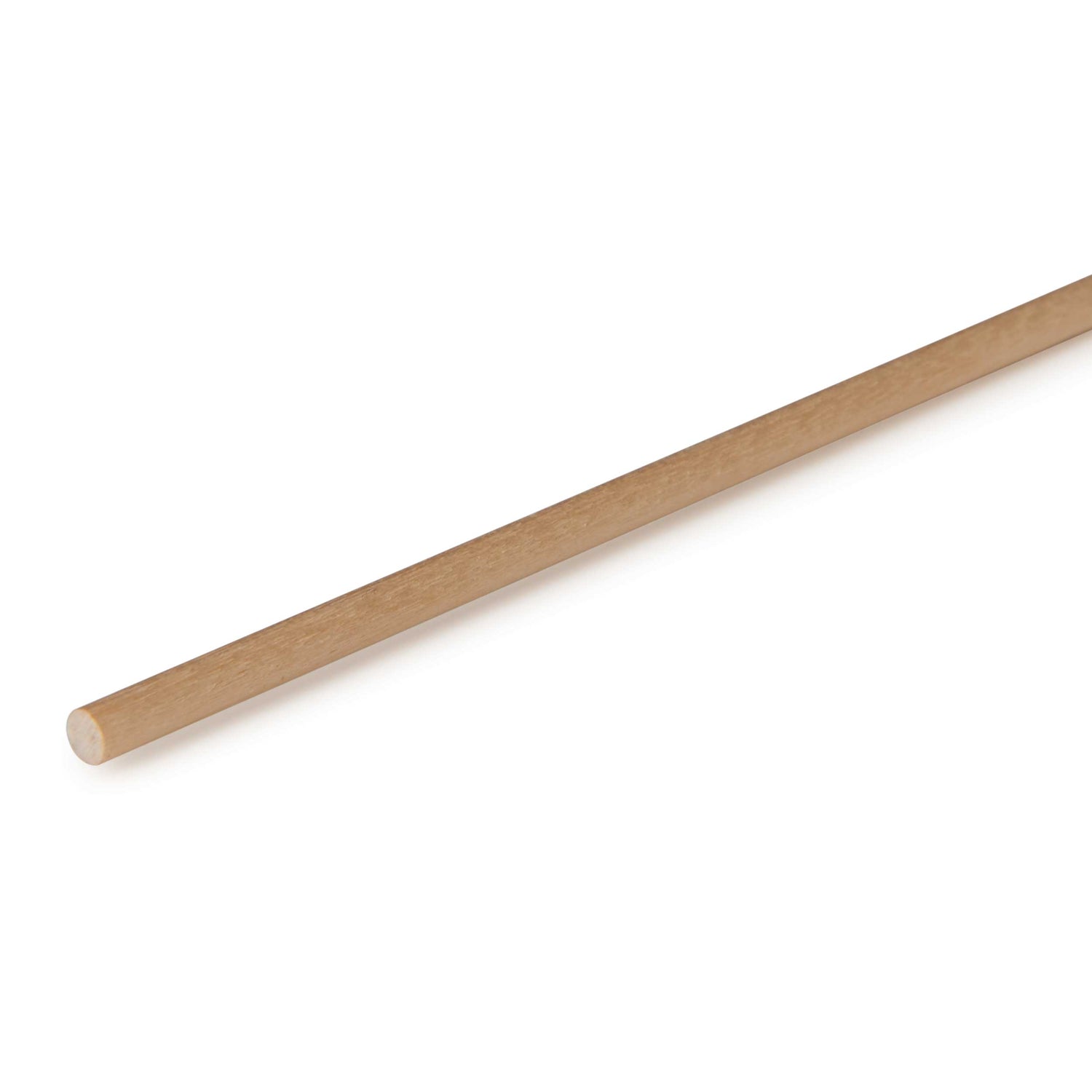
5 Make the Half-Tire Kerfing Jig in Figure 6, as shown, using a 3⁄4 ʺ-thick × 3ʺ-wide extension fence. (Check to see if the tire halves will turn on the dowels; if not, sand the dowels down.)

6 Install a 1⁄4ʺ dado set, and raise it to cut 3⁄16ʺ deep. Now, place the miter gauge to the left of the blade. Set it at 60°, as shown in Photo G. Position the jig fence on the miter gauge, aligning the marked alignment line with the inside edge of the dado set, and attach it with screws. Slip a test half tire onto the dowel, aligning the pattern start line with the alignment line on the top edge of the jig. Use a small clamp to hold the half tire to the fence. Turn on the saw and cut the half tire’s tread. Repeat by rotating and aligning the template lines for each kerf cut, making the final cut at the red stop line. Check the tread. The kerfs should be evenly spaced. Finish cutting the “right” group. To cut the “left” group of half tires, move the miter gauge to the left of the blade, and angle it to 60° in the other direction. Reposition the jig fence as described earlier. Cut the kerfs in the left group of half tires.
7 Remove the paper templates from the tire halves while keeping them in right and left groups. To bond the tire halves together, spread glue sparingly on the inside (unrounded) faces. You don’t want glue squeeze-out at the joint lines. Next, insert a
1⁄4 × 3ʺ bolt through a washer, the hole in the tire halves, through second washer, and tighten the halves together with a nut, as shown in Photo H. (Doing this keeps the halves flush.) As you tighten, adjust the halves to create an offset V-tread pattern. Similarly glue and clamp the remaining tires for two left-hand and two right-hand tires (N).
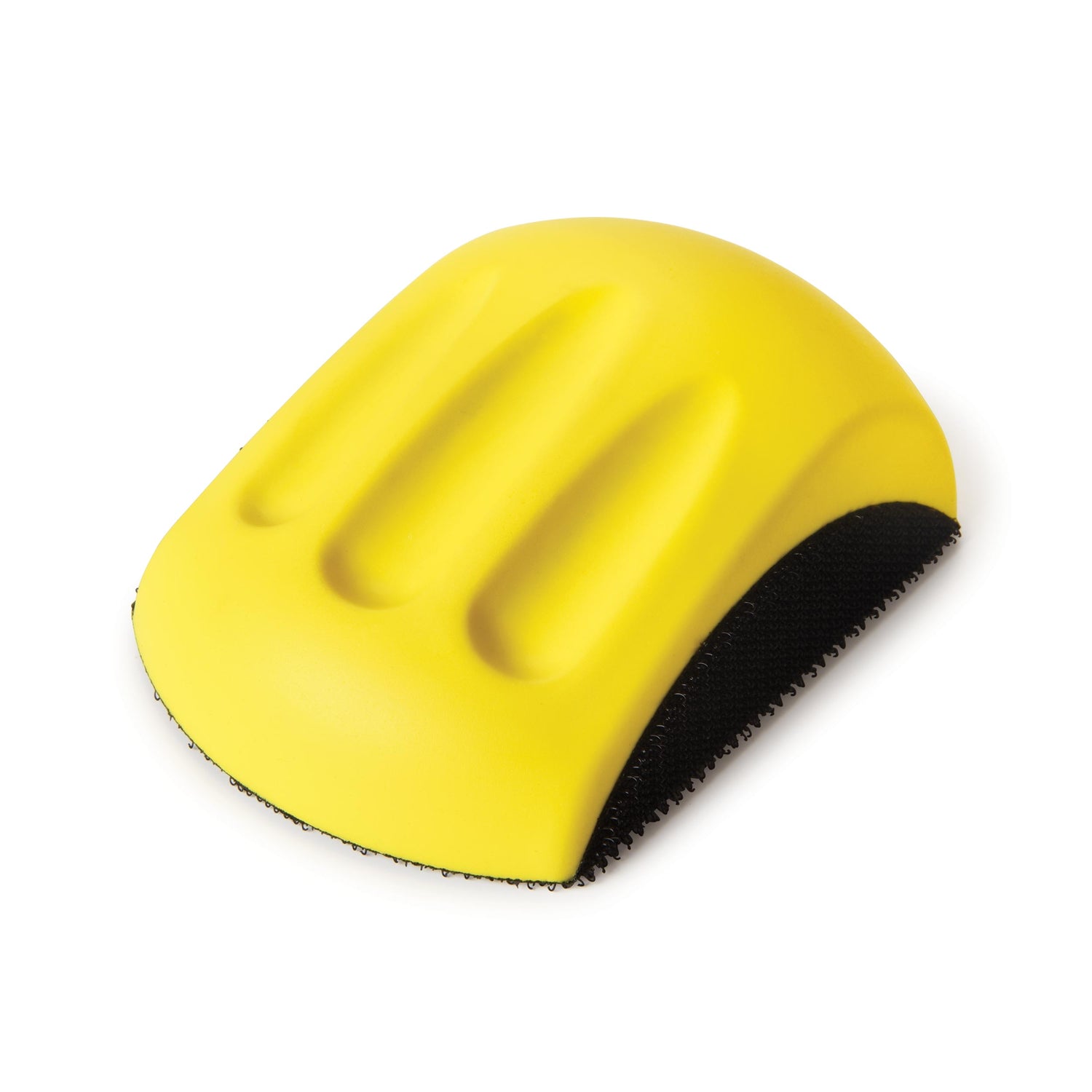
8 After the glue dries, install the bolt of a tire assembly into the drill press chuck. Turn on the drill, and sand away any burn marks on a tire (N), using a sanding block with 80-grit sandpaper. Repeat for the remaining tires.
9 Install an 11⁄32ʺ brad-point bit in the drill press and, using the tool’s fence and stopblock, align it with a tire’s 1⁄4ʺ hole and 1⁄8ʺ-deep recess hole made previously. Widen the hole so an axle peg can slip through it. Repeat for the remaining tires and finish.


Center the brackets between the bucket sides, and glue and screw them in place, using a 35⁄8"-long L-spacer.

Make the bucket
1 From two 3⁄8ʺ maple blanks measuring 6" wide × 5 1⁄4" long, cut the bucket bottom (O), small angle (P), bucket back (Q), large angle (R), and Top (S), referring to the Cut List, Figure 5, and the Bucket Patterns. Note that all the parts except the top have two bevel cuts at 22 1⁄2°. The top has one 0° (or 90°) edge and one 22 1⁄2° edge. To make the cuts, use a miter gauge and extension fence, sawing similarly to how you cut the cab parts earlier by flipping the blanks. Here, lay out the edges of each cut to the needed toe-to-toe widths. (I laid out and cut the parts as follows: S, Q, R from the first blank and P and O from the second blank.)
2 To form the bucket shape, you'll need to make two spacers that will be cut to the bucket’s interior size and shape, starting with a 1⁄2 × 2 3⁄4 × 3 3⁄4ʺ piece of MDF. Make the cuts shown in the Bucket Parts End View in the Bucket Patterns. Tape the bucket parts (O, P, Q, R, S) edge to edge. Then fold them around the spacers to check their fit. Glue up the assembly (Photo I).
3 To make the bucket sides (T), place the assembly (O, P, Q, R, S) on end on a 3⁄8ʺ-thick piece of maple and trace around it. Repeat the process on for a second side shape. Draw a diagonal line on each shape, where shown in the Bucket Parts End View. Bandsaw the sides, cutting just outside the lines.
4 Attach the bandsawn sides (T) to the bucket assembly (O, P, Q, R, S) with glue and 3⁄4ʺ pin nails. Sand the proud bandsawn edges of the sides flush with the bucket assembly, and break the edges.
5 From two 3⁄8ʺ-thick maple blanks, make the arm (U), knuckle (V), and bracket (W). To do this, make two copies of each full-sized pattern in the Bucket Patterns, and adhere them to the blanks. Then bandsaw or scrollsaw the parts to shape. When cutting the brackets to shape, double-check for a tight fit against the bucket shape. Sand or recut if needed. Drill the shank and pilot holes where indicated. Remove the patterns, and sand the sawn edges smooth, breaking any sharp corners.
6 Make an L-shaped spacer using two pieces of 1⁄2 × 21⁄2 × 35⁄8ʺ MDF. Glue and pin-nail the pieces together to form the “L.” Center and place the spacer on the bucket between the ends. Now, apply glue, position, and clamp the brackets (W) to the spacer, ensuring they’re snug to the bucket. Drill pilot holes into the edges of the brackets, where shown in the pattern, and screw them in place (Photo J). Add two more screws from inside of the bucket. (See Figure 5.)

Download the patterns from onlineEXTRAS, below.
Finish-sand, apply finish, and assemble
1 Finish-sand all of the parts and assemblies to 220 grit. Wipe clean, and apply finish to the assemblies and unassembled parts. (I used Watco Satin Lacquer.) Apply finish to just the exposed ends (not the shanks) of the axle parts. Let the finish dry.
2 Assemble the two frames (A, B). To do this, place a fender washer between the two frames and on the #8 × 1 1⁄2 ʺ roundhead screw before you drive it in place. (Tighten or loosen the screw to get the right pivoting action.)
3 Orient the left and right tires (N) so the recessed faces are on the outside. Place a small amount of glue in the axle peg holes, and then push the axle pegs through the tires. Fit nylon washers on the pegs, and then tap them into the frame holes, leaving a clearance equal to the thickness of a business card for the tires to turn freely. Pin-nail the pegs to the frames (A, B).
4 Attach the bucket parts with roundhead screws and washers, as shown in Figures 1 and 5. Do not overtighten.


