Tackle the mortise work with a simple shop-made jig.
Overall Dimensions: 35"w × 72"l × 29 1⁄2"h
Trestle tables are one of the oldest and most popular furniture designs for many solid reasons. Homeowners love how a trestle table’s clean lines complement almost any interior décor and appreciate the way the I-beam base provides more leg room for diners than traditional four-legged tables with aprons. Woodworkers gravitate to the design for more practical reasons. Compared to other designs, trestle tables are simple to build and make surprisingly efficient use of material. In addition, the top can be removed, enabling this large project to be easily shuttled from the workshop to the dining room.
My table is solidly rooted in eighteenth-century Shaker design, but I made a few changes to suit a modern woodshop. Most noteworthy is my use of loose tenons to attach the breadboard ends and to assemble the table’s base. With help from a plunge router equipped with a spiral bit and my multipurpose mortising jig, you can quickly and accurately make the needed joints while bypassing more time-consuming traditional methods.
Despite its airy appearance, this table is built to last, so take your time when selecting stock and pay close attention to symmetry and grain flow when laying out parts. Odds are good that your kids will pass this table down to your grandkids.
Builder’s note: To avoid the hassles that come from mid-construction wood movement, mill all stock to rough dimensions (about 1-2" longer and 1⁄2"wider) prior to working on each subassembly. Mill and assemble each subsection before moving to the next.

Make the top
1 Select your most attractive 5/4 material for the top (A) and breadboard ends (B), and match your boards edge to edge. (When working with rough-sawn stock, I take a few passes with a hand plane to reveal the grain.) After orienting the boards in their desired configuration, number the end-grain surfaces for reorientation after final planing.
2 Joint and plane the boards for the top (A) (see “Tabletop Tips,” below) and breadboard ends (B). Referring to the Cut List, rip the middle boards to width, but leave the two outer boards 1⁄4" wider. (At this point, leaving the boards long allows you to slide them back and forth to achieve the best grain match.) Mill the breadboard ends to match the top’s thickness, and cut them 2" longer than final length.
3 Arrange the boards in their original orientation, and glue up the top. Position the clamps every 16", alternating them on either face to prevent bowing.
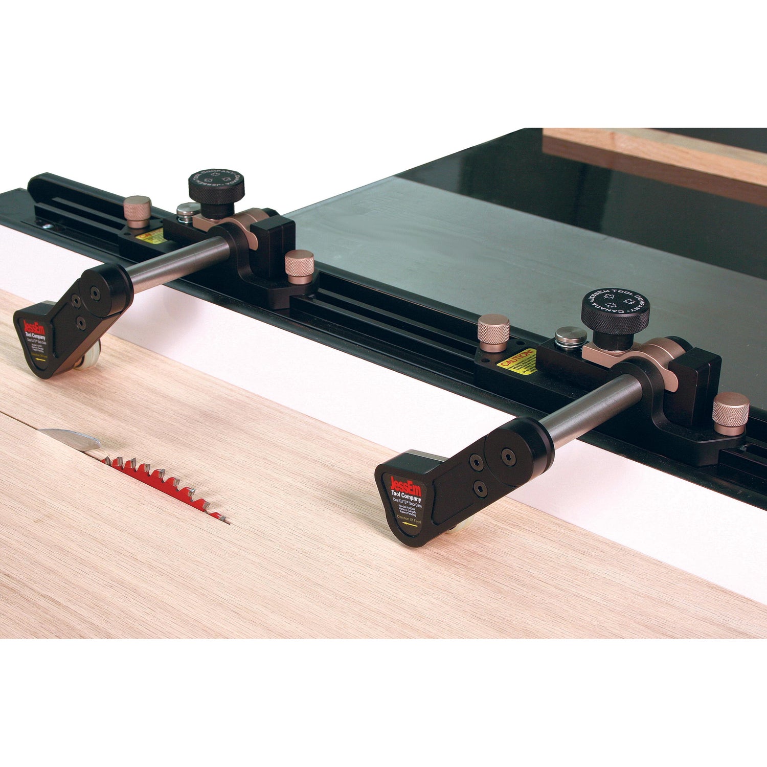
4 After the glue joints have cured, rip 1⁄4" off of each side at the tablesaw. Using a router, cut a 1⁄8" chamfer on the long edges of both the top and bottom faces. Next, crosscut the top panel to 63" long. To do this, I used a track saw (Photo A). Alternatively, you can use a standard portable circular saw and a store-bought or shop-made straightedge guide.
Tabletop Tips
Even on a well-matched panel, a glue line running down the middle of a tabletop can attract unwanted attention. To avoid this, make the top from an odd number of boards. For a 6" jointer, this means seven 5"-wide boards, or five 7"-wide boards if you own an 8" jointer. When thicknessing, consider leaving your stock 1⁄32" thicker than final thickness in case the top requires flattening after assembly.


Align the jig’s crosshairs with the centerlines on the breadboard end, clamp the jig in place, and then rout the breadboard end mortises.
Add the breadboard ends
1. Make the mortising jig shown below.
2. Clamp the breadboard ends (B) face to face to the top (A) so that the inner edges are flush with the ends of the top and the breadboards are centered across the width of the top. Then lay out the mortises on the adjacent parts, where shown in Figure 1 and as shown in Photo B. Mark the parts so that they remain paired with their mate and maintain the same orientation throughout the assembly process.
3. Using a plunge router equipped with a 3⁄4" guide bushing and a 1⁄2" spiral upcut bit (see the Buying Guide), rout the 1 1⁄2"-deep mortises on the top and breadboard end, as shown in Photos C and D. (Note: To ensure that the mortises line up, orient the jig so that the fence registers against the same face of the top and breadboard end through the routing sequence.)
4. To make the loose tenons (C), first thickness hardwood strips to 1⁄2". (Test the stock on the actual mortise. Aim for a friction fit.) Then, rip the strips to 3" wide. To allow the top (A) to move independently of the breadboard end (B), rip enough material to make twelve 2 1⁄2"-wide outer tenons for the top (A). Next, round over the edges of the strips to match the mortises. (I used a 1⁄2" half-round bit in the router table; alternatively, you can use a 1⁄4" round-over bit and finish each edge in two passes.) Now, cut the tenons to length.
5. Apply glue to the mortises in the top (A), and insert the loose tenons (C). Next, draw centerlines across the width of the center and two outermost tenons, and extend mortise centerlines onto the top face of the top (A).
6. Dry-fit the breadboard ends (B) to the top (A), and extend the centerlines you made in the previous step onto the top faces of both breadboards. Referring to Figure 1, mark out the holes for the pegs. Using a drill and 5⁄16" brad-point bit, bore both center peg holes through breadboard ends and center tenons. Next, remove the breadboards, and then drill the outermost peg holes through just the breadboard ends.
7. Reassemble the top, and apply clamping pressure to draw the breadboard ends tightly against the ends of the top. Now mark the holes in the outermost tenons by first inserting a handheld 5⁄16" brad-point bit into each outermost hole in the breadboard ends, and twisting the bit while pressing it against the tenon. Then remove the breadboard ends, and mark a point on each tenon inward 1⁄16" from the drill point mark. Use the 5⁄16" bit to bore a hole through each tenon at this new point. Referring to Figure 1, lay out a pair of lines tangent to each outermost hole and parallel to the ends of the top. Using these lines as guides, carefully create the 3⁄4"-long slots using a round file or chisel (Photo E).
8. Plane a slight (1⁄16") chamfer along both ends of the top and inside edges of the breadboards. Then, brush glue onto the center tenon only, and put the breadboard ends (B) back in place. Cut six pegs about 1⁄2" longer than the thickness of the breadboard ends, and use a pencil sharpener to chamfer the ends for easier insertion. Drive the center peg completely through the top (A). Next, drive the outer pegs halfway in, coat the holes on the underside of the table with glue, and then drive the pegs through the joint. Finally, saw and then sand the pegs flush with the top.
9. Trim the breadboard ends (B) to length. To do this, I clamped a straightedge parallel to the top’s edge and routed the overhanging portion with a bearing-guided spiral bit. Alternatively, you can saw and plane the ends. Just make sure to plan for future wood movement (see “Seasonal Considerations”, facing page).
10. Rout a 1⁄8"- wide chamfer along the outside edges of the breadboard ends to match the top. Set the assembled top (A/B) aside for now.
Seasonal Considerations
Because the top moves independently from the breadboard ends, it’s important to consider the time of year when trimming the ends. When building during the humid months, it’s OK to cut the ends flush because the top is likely to shrink. In drier months, trim the breadboard ends 1⁄8" to 3⁄16" longer (on both sides) so that the top will not expand past the breadboard end when the weather changes.


Make the base
1. From 8/4 stock, mill two pieces of wood to 1 1⁄2 × 7 1⁄2 × 24". Mark a centerline across the width of each board, and extend that line across the top edge. Using the pattern on page 43, make a half-pattern of the foot. Align the pattern with the centerline on the face of a foot blank, trace the pattern, and flip the pattern on the centerlines to draw the complete foot (D).
2. Set the mortising jig fence to rout a centered slot in 11⁄2"-thick stock. Next, align the centerline on the jig panel with the mortise centerline, clamp the fence to the top edge of one of the foot blanks, and then plunge-rout a 1⁄2 × 3 × 11⁄2" mortise (Photo F). Repeat with the other foot blank.
3. Using a bandsaw, cut each foot to shape, staying just outside the lines. Finish shaping the feet using a combination of hand tools and machinery. (As much as I enjoy using a spokeshave, as shown in Photo G, there’s nothing wrong with using a disc sander on the convex edges and a spindle sander to tackle the concave sections.) Rout 1⁄8" chamfers along the outer edges, where shown in Figure 1. Leave the bottom-most edges unchamfered.
4. From 5/4 stock, mill the material to make the posts (E) and stretcher (F). Cut the parts to the sizes listed in the Cut List (see onlineEXTRAS, below). Put the stretcher aside for now.
5. Referring to Figure 1, lay out centerlines on the ends of both posts (E) for the blind mortises. Also lay out (on the outside face of each post) the through mortises that will accept the stretcher (F) tenons. Include centered crosshairs to aid in the placement of the jig when setting up to cut the through mortises.
6. Adjust the jig to rout a centered mortise on 1 1⁄4"-thick stock, and then rout the 1⁄2 × 3 × 1 1⁄2" mortises on both ends of each post.
7. Remove the jig’s panel from the fence, and apply double-sided tape to its bottom face. Now align the panel’s crosshairs with the crosshairs on the outside face of a post (E), and clamp the panel to the post to ensure a good bond. Rout the through mortise, and then carefully pry off the panel (Photo H). Repeat with the remaining post.


8. Using a mitersaw, crosscut a small block to 87°. Clamp the block to one end of the mortise on the outer face of a post, and use it as a chisel guide to flare the ends of the mortise (Photo I) so that the wedges will lock the stretcher (F) to the posts (E).
9. Using a handsaw (Photo J), or else a dado set and miter gauge outfitted with an auxiliary fence, cut the 1⁄2 × 3 × 1 5⁄8" tenons on both ends of the stretcher (F). (Note: You want the tenons to stick through the posts by at least 1⁄8".) Referring to Figure 1, kerf the tenons for the wedges. Finally, rout a 1⁄8" chamfer along the outside edges of the stretcher.
10. From 8/4 stock, cut the braces (G) to the dimensions in the Cut List, and saw a 45° chamfer on the ends, where shown in Figure 1. Rout 1⁄8" chamfers along the ends and bottom edges of both braces.
11. Lay out mortise centerlines on the top face of each brace (G). Adjust the mortising jig fence to rout a centered slot in 1 1⁄2"-thick stock, and then rout the mortise in each brace. Finally, use a drill press to bore the 3⁄4 × 3⁄8"-deep blind holes and the 5⁄16" through holes used to attach the base to the top (A/B).
 Finish and assemble the table
1 Brush glue into both end mortises on one post (E), and insert a loose tenon (C) in each. If needed, use a bar clamp to ensure that the tenons seat completely in the mortises. Wipe away any excess glue that squeezes from the joints that may interfere with future assembly. Allow the glue to dry, and then apply glue to the foot (D) mortise, and clamp the pieces tightly together. Repeat with the other post and foot. Drill 5⁄16" holes for dowels, where shown in Figure 1, insert dowels, and then trim flush. (Note: A properly glued loose-tenon joint doesn’t need reinforcement, but I used pegs in case the glue should fail sometime in the future.)
2 Referring to Figure 1, saw out four wedges to secure the leg assemblies to the stretcher (F). (When selecting a contrasting wood, choose a split-resistant stock such as oak or ash.) Apply glue onto the cheeks of the stretcher’s tenon, position the stretcher between the two foot/post assemblies (D, E) and then use clamps to draw the tenon shoulders against the posts. Apply glue into the kerfs and onto the wedges. Then, tap the wedges in, as shown in Photo K. When dry, trim the wedges flush.

3. Brush glue into a brace (G) mortise, place it onto the loose tenon projecting from the top end of a post (E), and then clamp the two together. (To avoid denting your project, position a block of softwood or rigid foam between the clamp and bottom edge of the foot.) Repeat with the remaining brace. Drill 5⁄16" holes for dowels, where shown in Figure 1, insert dowels, and then trim flush.
4. Cut the footpads (H) to the dimensions listed in the Cut List. Plane or rout a 1⁄8" chamfer along the top edges, and then attach the pads to the ends of the feet with glue and 1 1⁄2" screws. (Countersink the shank holes so that the screw heads can’t scratch.)
5. Sand the assembled top (A/B) and base (D-G) through 220 grit, and then apply the finish of your choice. (I applied two coats of General Finishes Enduro-Var on the base [sanding between coats with 360-grit Abralon sanding pad], and four on the top. After allowing time for the finish to cure, I finish-sanded the surfaces with a 500-grit pad, and then applied a coat of wax.)
6. Center the base on the underside of the top, and attach it using 3⁄4" washers and 2" washer-headed screws (Photo L).

About Our Author
Chris Hedges discovered his passion for furnituremaking after beginning a career as a sociology professor. He then enrolled in the University of Rio Grande’s woodworking program, and soon thereafter won the 2007 Freshwood Competition for his highboy secretary. Chris now runs AedanWorks from his home in Athens, Ohio, and works at the Woodcraft retail store in Parkersburg, West Virginia.


