Discover an intriguing way to hang drawers.
Overall dimensions: 14"w × 9 1⁄2"d × 8 3⁄4"h
This Asian-influenced box, with its broad beveled top and pagoda styling, features a drawer-hanging system that doubles as a dominant design element. Contrasting woods contribute to the overall look, as do the custom-made pulls. Splines join the mitered drawer corners, while the V-grooves cut in the drawer sides provide purchase on the wooden slides attached to the legs.
Precision setup and machining are key in the construction, made possible by a collection of simply-made jigs. I’ll walk you through a successful building experience, so that, in the end, you’ll have a worthy holiday gift item and a bucketful of new skills guaranteed to pay forward on later projects.


Align the point of the V-groove bit with the appropriate line on the setup jig to accurately adjust the fence. Lock the fence in place.


Build the open sides
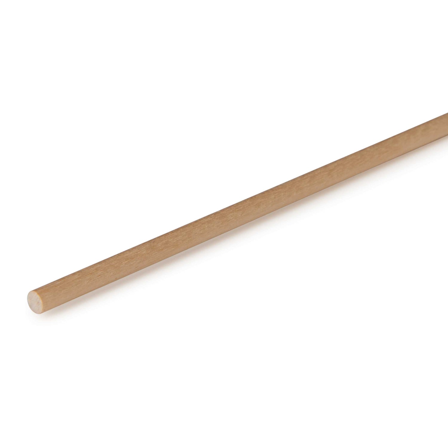
1 Rip two 48"-long walnut strips to 11⁄16" square and then surface them to 5⁄8" square. Crosscut the strips into eight 9"-long pieces for the drawer slides (A) shown in Figure 1.
2 Chuck a chamfering bit into a table-mounted router and, using a miter gauge or pushblock, cut 1⁄16" chamfers at the front ends of the slides (A).
3 Rip a 40" length of 6/4 (1 1⁄2"-thick) walnut stock to 15⁄16" square. Now, surface the piece to 1 1⁄4" square. Set up a stop on a tablesaw or mitersaw and cut four jewelry box legs (B) to the Cut List length.
4 Lay out the V-grooves precisely where shown in Figure 2 on MDF or scrap plywood for a setup jig.
5 Next, install a 90° V-groove bit in your table-mounted router. Using the setup jig, adjust the fence, as shown in Photo A. Routing in increments, cut a 5⁄16" V-groove in the jig where shown in Figure 2. Use it to establish the needed bit height for the final pass for each leg V-groove.
6 Cut the V-grooves across one face of each leg (B). Rout the top groove in all four legs first before moving to the next set of four V-grooves. Adjust the fence for each set, making three or more passes per set until the V-grooves measure 5⁄16" deep. When making the cuts, back the workpieces with a miter-gauge extension fence or wood block, as shown in Photo B, to prevent tear-out. Before taking down the setup, lay the slides (A) in the grooves for two legs that make up one side. Place a straightedge across the slides to verify that they lay flat and are at the same height. Tweak any nonconforming cut.
7 Use the same bit to chamfer all four corners of the legs (B), where shown in Figure 1. With the bit raised to full height, cut the chamfers in increments, adjusting the fence as needed. Stop cutting when the edges of the chamfers intersect the point of the V-grooves. Sand the flat surfaces of the legs to 150 grit.
8 Referring to Figure 3, make the Side Glue-Up Jig and two 6"-wide spacers from scrap.
9 Set the legs (B) for the left and right side assemblies in the jig, spacing them 6" apart with the spacers. Apply glue in the V-grooves for one side assembly, and set the slides (A) in the grooves. Ensure that the innermost leg and back ends of the slides are flush by snugging them against the jig’s center rail. Also make sure the front leg is snug to the spacer. Use a clamped or weighted caul to press the slides firmly and evenly into the grooves. Repeat for the remaining side, as shown in Photo C. Remove any squeeze-out around the slides.
10 Attach a sacrificial fence to the tablesaw fence and install a 1⁄4" dado set. Raise the blade to 3⁄8". Now, referring to Figure 1, cut the rabbets on the back ends of the slides by running the side assemblies (A, B) along the fence.
11 From 1⁄4" stock, rip a 3⁄8"-wide piece long enough for the two drawer stops (C). Crosscut the pieces to finished length, test their fit in the slide rabbets, and then glue and clamp the stops in place.


Use a simple jig and spacers to build box sides that mirror each other.

Add the top to the sides
1 From 4/4 (1"-thick) walnut stock, glue up a blank to make the finished top (D). Trim the piece to the size in the Cut List. (If you have a piece wide enough, go with that.) Now, plane the blank to 3⁄4" thick and finish-sand, ensuring flat surfaces.
2 Chuck a bevel-profile raised-panel bit in a table-mounted router. As shown in the Raised-Panel Profile in Figure 1, you’ll want the final cut to result in vertical edges bordering the tapered section to be equal in width. Shape the top (D) in steps, profiling the cross-grain ends first and the long-grain edges second to minimize tear-out. Sand the surfaces to 180 grit.
3 Construct the Right-Angle Drill-Press Fence in Figure 4.
4 Mark the center on the top of each leg (B), and then chuck a 3⁄8" Forstner bit in your drill press. Holding a side assembly to the drill-press fence, drill a centered 3⁄4"-deep hole in each leg, as shown in Photo D. Do the other side assembly too.
5 Build the Dowel-Hole Positioning Jig in Figure 5 from scrap. When in use, this spacing jig ensures that the distance between the side assemblies (A, B, C) is the same at the front and back and that the assemblies stand vertically.
6 Insert 3⁄8" dowel centers in the leg holes, and place the side assemblies against the positioning jig, as shown in Photo E. Center the top (D) on the leg assemblies, and press down to mark for the locations for the mating dowel holes (see Figure 1 for reference).
7 With the 3⁄8" Forstner bit, drill 1⁄2"-deep holes in the underside of the top (D) at the marks.
8 Trim 3⁄8" dowels to just under 1 1⁄4" long. Now insert them in the leg holes, and dry-fit the top (D) onto the legs (B) to make sure the dowels seat fully. Now, apply glue to each hole and dowel, and attach the side assemblies (A, B, C) to the top (D). Check the alignment with a square, and adjust the side assemblies vertically if needed.


With the slot-cutting bit installed (Inset), hold the mitered workpiece snug to the jig’s fence and make the cut.

Machine the Drawer Parts
1 Referring to the Cut List, prepare enough stock for the drawers by surfacing a maple board to 9⁄16" thick. (Because I used tiger maple for the fronts, I actually surfaced two separate boards to that thickness.) Now rip the stock to 1 7⁄8" wide. Cut the fronts (E), backs (F), and sides (G) 1⁄2" longer than their final lengths.
2 Set up the tablesaw for a 45° miter cut, and then miter one end of each drawer piece (E, F, G), removing about 1⁄4" in the process. Now, using a stop, cut the drawer fronts (E) and backs (F) to 10" (Photo F). Adjust the stop and cut the sides (G) to 8".
3 Build the Spline Slotting Jig in Figure 6 to hold the drawer fronts (E), backs (F), and sides (G) at a 45° angle to the router table while cutting spline slots perpendicular to the mitered ends.
4 Install a 5⁄32" slot-cutting bit in the router table. Now, adjust the bit height to cut a slot in the mitered ends of drawer parts E, F, and G 1⁄8" in from the inside faces. Adjust the fence to cut 1⁄4" deep into the wood, and slot-cut the parts (Photo G).
5 Rip the drawer fronts (E), backs (F), and sides (G) to final width, removing any edges with tear-out if needed.
6 Adjust the saw blade to 3⁄16" high, and move the fence 5⁄32" from it. Now, make the first groove cuts for the drawer bottoms (H) on the inside faces of the drawer fronts (E), backs (F), and sides (G). Using the plywood for the bottom as a gauge (I used 5⁄32"-thick material), adjust the fence and make a second cut in one piece and test the fit. If satisfied, enlarge the grooves on the other parts.
7 Lay a ruler in the drawer bottom grooves cut in step 6 to measure the length and width required for the bottoms (H). Measure the bottom groove length of one front (E) or back (F) and a side (G).
8 Cut the bottoms (H) to size and test-fit. The bottoms can be 1⁄32" shorter all around with no problem.
9 Finally, measure the length of the grooves on the drawer parts (E, F, and G) to where they intersect the spline slots. Then use a fine-tooth handsaw to nip off the corners of the bottoms (H) to those dimensions to provide through clearance for the splines. (I usually cut off about 3⁄16" from each corner, but measure first to verify.)


Working off the stand-off to establish the width of the finished pull support, hold the workpiece to the extension fence and make the 25° cut.
Cut the splines and assemble the drawers
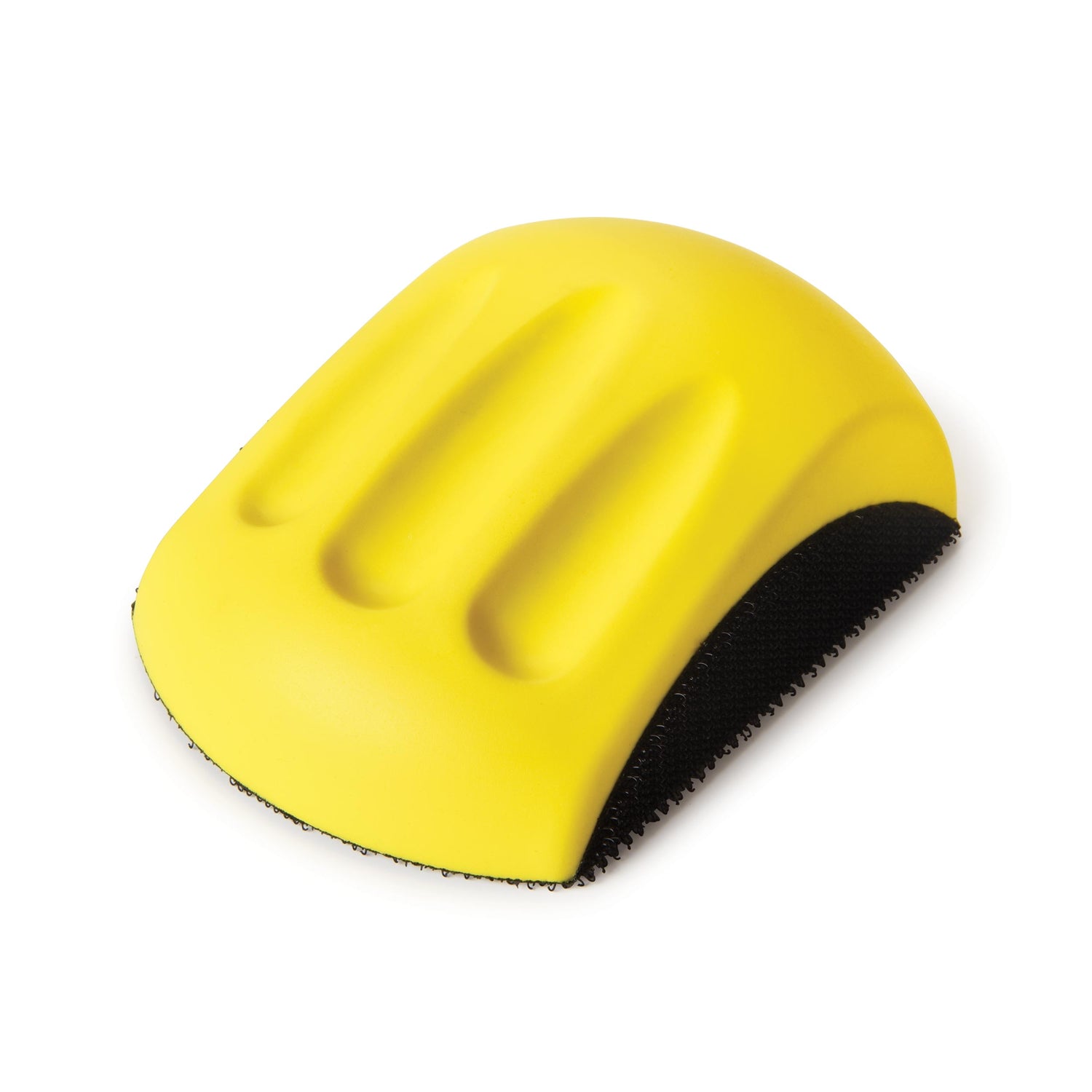
1 Using a carrier board, plane a piece of 2"-wide walnut stock to a hair over 5⁄32" thick for the splines (I). Test-fit an edge of the piece in a spline slot. Sand the piece, if needed. (I used a drum sander to sneak up on the fit, but a simple handheld block sander would suffice.) You want a sliding fit in the slots with no slop.
2 Next, determine the width of your spline stock by first clamping the parts of one drawer (E, F, G, and H) together. Now, measure the total width of the two adjacent spline slots at one corner. (Ideally, it should be exactly 1⁄2".) Set up a stand-off on your tablesaw fence, and trim one cross-grain spline (I) to the width determined. Test-fit the piece in the assembled drawer. Adjust the width if needed, and cut the remaining splines (you need a total of 16). Consider dry-fitting the other drawers and test-fitting all of the splines for a precision fit.
3 Sand the inside faces of the drawer fronts (E), backs (F), sides (G), and both faces of the bottom (H) to 150 grit.
4 Dry-fit the drawer parts for one drawer (E, F, G, and H), inserting the splines (I) and clamping the assembly with a band clamp. Check it for square and gapped joints. Make any needed corrections. Now, disassemble and apply glue to the spline slots and the mitered surfaces. Reassemble the drawer, pulling the parts together with the band clamp.
5 Apply a light coat of glue to the splines and tap them into the corner joints, as shown in Photo H, making sure they bottom out. Check that the drawer is still square, and tighten the clamp. Remove any squeeze-out. Once the glue dries, remove the clamp and then cut and sand the splines flush with the box edges. Repeat for the remaining drawers.

Fit the drawers to the side assemblies
1 Measure and mark the exact center of the drawer sides (G). Now, install a horizontal V-groove bit in the router table, and adjust the fence so that the bit’s point is dead center on the center mark.
2 Take an initial cut of around 3⁄16" deep. Now, make an initial pass on both sides of the drawers, using a backer board to minimize chip-out. Make subsequent passes as shown in Photo I, increasing the depth each time and testing the fit of the drawer into the frame. The final groove should be about 5⁄16" deep, but check each drawer’s fit when making the final passes. This is where even minor variations in dimensions and tolerances come into play. The final fit should slide freely without slop. For the best fit, mark each drawer on its bottom outside face as to its intended location in the box.
3 With the drawers fitted, lower the router bit to cut a 1⁄8" chamfer along the top and bottom edges of all the drawer sides.
4 Final-sand the drawers to 180 grit.
5 Make the top and bottom egg-crate dividers (J, K), shown in Figure 7, for one or more drawers by first planing and ripping strips to the thickness and widths in the Cut List. Next, rout 1⁄8" round-overs on the top edges on each strip. Now, crosscut the needed number of pieces to length after confirming the dimension with the drawers. Bundle the top dividers into one group and the bottom dividers into another with double-faced tape, flushing the edges and ends. Lay out the 1⁄4" notches 5⁄16"-deep on the top piece of each bundle, where shown in the drawing, and cut them with a miter gauge and an extension fence outfitted with stops. Assemble the egg-crate dividers and test-fit them in the drawers.


Make the stylish pulls
1 Cut a 20"-long piece of stock to 1⁄2" thick × 7⁄8" wide for the pull supports (L). Mark across the width of the stock for correct reassembly after it has been ripped.
2 Referring to the five-step sequence in Figure 8, raise your saw fence to 5⁄8", rip a 1⁄8" piece off of the stock’s width, and set the 1⁄8" piece aside.
3 Using a flat tooth grind (FTG) blade in your tablesaw, raise the height to 1⁄4" and make a test cut to achieve the exact dimension. Now, adjust the fence 1⁄8" from the blade. With the ripped edge of the narrow strip down, make the first of two adjacent groove cuts. Turn the piece end for end and make the second cut to create a 1⁄4"-wide groove, 1⁄4" deep.
4 Apply a thin layer of glue to the inside surface of the 1⁄8"-thick strip. Align the strip with the marks on the grooved piece and then clamp it in place using spring clamps to hold it tight and flush. Remove any squeeze-out and let dry.
5 Square one end of the blank and lay out the first pull support (L). Angle the miter gauge and extension fence at 25°, and clamp a stand-off to your saw’s fence so that, after cutting the pull support, the wider end of the support measures 5⁄8" wide. Now, position the stock against the miter gauge extension fence, making sure that the narrower side above the square hole touches the fence. Cut off a pull support. Square the workpiece before cutting the next pull support. (I alternate the miter gauge between the 90° and 25° settings.) Continue cutting (Photo J) until all eight pull supports are made. Sand the cut surfaces to remove chip-out and saw marks.
6 Measure the width and depth of the square hole in a pull support (L) for the pull bars (M). Next, rip stock for these pieces to this exact dimension or slightly over, and sand for a good fit. Cut four pull bars to the Cut List length, and check that they slide through the holes.
7 Cut a 2 1⁄2"-wide spacer block to align the pulls for glue-up. Now, position two pull supports (L) at opposite ends of the spacer block. Insert and center the pull bar (M) in the square holes in the spacer blocks. Slide each pull support off slightly, place a drop or two of thin CA glue at the joint location, and reposition the supports. When the glue has set, lightly sand the assembly. Repeat for the remaining pull assemblies.
Attach the drawer pulls
1 Strike a centerline lengthwise on the drawer fronts (E). Next, draw lines corner to corner across the wide end of each pull support (L) to locate the centers.
2 Snip the heads off eight 3⁄4" brads. Grasp the cut end of a brad in a drill chuck, and spin the brad into the pull support at a marked center. Do this for all the pull supports.
3 Mark one end of each pull assembly (L, M) as “left”, and number each assembly 1-4. Similarly mark the drawers. Now, carefully locate the brad points of one pull assembly on a corresponding drawer front (E), guiding on the centerline. Use spacers or an adjustable square to precisely center it between the drawer front ends and edges, and press the points into the wood (Photo K). Do the same for the remaining assemblies.
4 Pull the brads with pliers. Now, set up the drill press and, using a brad-point bit, drill 1⁄8"-diameter holes, 1⁄4" deep in both the drawer fronts (E) and the pull supports (L).
5 Crosscut 1⁄8"-diameter dowels to 7⁄16" long. Insert them in the pull assemblies (L, M) and test-fit them in the corresponding holes in drawer front (E). Check that they align drawer to drawer in the jewelry box. Now, remove the pull assemblies, add a drop or two of thin CA to the dowels, and press the assemblies in place.
6 Finally, finish-sand the box, and apply a clear finish of your choice (I used Deft Lacquer). Cut cardboard and drawer liner material to size. (I used metal-friendly Microsuede found at fabric stores, since it doesn’t chemically react with jewelry). Fit them in place (Figure 6). For more, see “Lining Drawers with Fabric,” from the April/May 2010 issue of Woodcraft Magazine.

About Our Designer/Builder
Bob Dickey’s background in design and engineering prepared him well for professional-level woodworking. In Mukwonago, Wisconsin, his home, he operates a gallery where he sells a variety of creative woodworking items. (Visit woodnonline.com). Bob also teaches at the Milwaukee area Woodcraft store.


