
You don’t have to be an artist to draw great furniture plans.
Woodworking requires a graphic language to convey building information. We can’t do it without drawings that show component relationships, joint sizes, offsets, profile shapes, and a myriad of other details. Most published woodworking plan illustrations are presented in pictorial fashion–representing the three-dimensional way we normally perceive objects. That’s great for a quick-hit understanding of construction, but it’s not always the best way to present certain information, and it doesn’t render the true profiles of the parts. Plus, pictorial representation probably doesn’t help you design your own project plans since, let’s face it, most of us aren’t artists.
That’s where orthographic, or multi-view, drawings come in. An orthographic drawing presents a “straight-on” two-dimensional view or views of an object as seen from, for example, its front, sides, and top. This shows parts in their proper shapes, proportions, and relationships while allowing easy dimensioning. Just as importantly, basic orthographic drawing is well within the reach of any woodworker who knows how to use a pencil, ruler, and drafting triangle, allowing you to create your own working drawings.
There’s no great mystery to orthographic drawings. Once you grasp the basic principles that I discuss here, you’ll be on your way to reading and writing one of woodworking’s most revered languages.
Think “inside the box”
Surely you’re familiar with the phrase “think outside the box.” With orthographic drawings, the opposite is true. You need to visualize an object as being inside a glass box, with the object’s various profiles projected onto the box’s sides. As shown in the series of drawings at right, first imagine each view projected onto its respective side of the box. Then unfold the box to display the views in their proper relationship to each other when represented on the page.
Since a box has six sides, you have the opportunity to illustrate the object in six views or elevations. Most furniture projects require only a front view, a side view, and occasionally a top view. Usually, the most descriptive view is selected to be the front view, which is placed in the lower left quadrant of the drawing. The right side view is placed in the lower right quadrant, and the top view (if needed) is placed at top left.

Construction lines
Several lines are commonly used to denote the outlines of parts and the location of holes. For the sake of discussion, I’ll call these “construction lines.” They include object lines, hidden lines, and centerlines, as shown in Figure 1.
Object lines are the most important of these. They represent all of the visual aspects of an actual object when viewed straight-on. For example, object lines show the perimeter of a cabinet as well as all the edges of its face frame, door, moldings, pulls, and every other line that the eye actually sees. On a drawing, object lines are rendered the thickest and darkest of all.
Hidden lines are used to depict any internal elements or features that are obscured in normal view, such as joinery or interior surfaces. These lines are rendered lighter and thinner than object lines and consist of a series of short dashes of equal length that are separated by spaces of shorter distance.
Centerlines are used to show axial symmetry, in which one half of the object is a mirror image of the other. Like hidden lines, they are lighter and thinner than object lines. A centerline consists of a series of short dashes, each of which is separated by a much longer dash. Centerlines are also used to locate holes, in which case the hole’s center point is marked by the intersection of two short dashes, each flanked by longer dashes.
To help clarify construction elements, a leader line (consisting of an arrowhead line and note) can be helpful, as shown identifying the drawer bottom in Figure 1. A leader can also be used to call out special details, hardware, or any other ancillary information.

A library of lines
This basic vocabulary of lines can be expressed nicely by the layman using a 5mm and a 9mm mechanical pencil outfitted with H and HB leads, respectively. But don’t let lack of the proper tools stop you; a regular pencil will get the idea across.

Sections
Details and part relationships represented by hidden lines can be confusing. This is where a section view can be helpful to further illustrate the main drawing. As the term implies, a section view shows parts as sliced through in cross-section, as shown in Figure 2. Parallel diagonal lines (cross-hatching in drafting parlance) are often used to indicate the area that has been “cut.”
A section line on the main drawing shows the source of the section view. It is at least as heavy as an object line, and it is depicted by pairings of twin short dashes separated by much longer lines. A section line terminates at each end with a perpendicular line capped with an arrowhead that denotes the direction from which the section is viewed. Letters adjacent to the arrowheads identify the particular section (in case there are several).

Breaks
If a part is very long (or very wide) with no unusual features along its expanse, break lines can be used to condense the amount of real estate given to the drawing. For wood parts, typical break lines are the same line weight as the object lines and are often shown as jagged edges (Figure 3). However, there don’t seem to be any strict conventions regarding the style of break lines. A zigzag dimension line can be used to identify the entire length of the interrupted piece.

Dimensioning
Once you complete your views, the next step is to dimension them. This is done using a combination of extension lines and dimension lines, as shown in Figure 4.
Extension lines project from the measurement’s points of origin without actually touching the object lines. Dimension lines terminate with arrows and span the distance between the extension lines to provide the desired measurement, which is noted at the center of the line. Note that extension lines extend a bit beyond the dimension line arrowheads. Both types of lines are lighter in weight than object lines.
Height dimensions are usually placed to the right side of the front view, where they can be shared with the right-side view. (Note that the height dimensions on the hybrid illustration/photo on page 31 were placed to the left only to suit this particular graphic.) Width dimensions are usually placed below the front view unless there is a top view, in which case the dimensions can be located between the two views.
Baseline dimensioning is a good approach for a project such as a chest of drawers that has lots of stacked elements. With this method, all height dimensions are taken off a baseline (usually the floor), with subassemblies and components called out individually. This helps eliminate errors caused by adding various height measurements to achieve a total. However, I prefer to take a modified approach, calling out just the most important dimensions.

For example, in Figure 5, I note only the distance to the top edge of each rail, which is all I need to lay out the leg mortises (or to create a full-scale story stick for the job).
Dimension lines denote door and drawer openings, but they typically do not include the gaps at the edges of the doors and drawers. That’s because these components are sized to suit the particular materials and any anticipated seasonal wood movement.
Although it doesn’t necessarily comply with conventional drawing standards, I use a simple approach to dimensioning spindles and other turned work. As shown in Figure 5, I list the diameters of a turning on the left-hand side of the drawing and the length dimensions on the right-hand side.

Getting started in drafting
Now that you understand the basics of orthographic drawings, you can make your own without investing in a lot of tools. In fact, you can make lots of rough orthographic sketches using nothing more than a pencil and a pad of quadrille paper (commonly called graph paper) with four squares to the inch. The paper allows you to easily scale your project down by assigning a convenient measurement (such as 1") to a square.
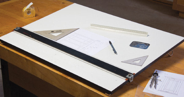
For much more flexibility and accuracy, get a few proper drafting implements. These include a T-square, a couple of triangles (30°/60° and 45°), a couple of mechanical pencils (a 5mm with H lead and a 9mm with HB lead should handle most of your needs), and a compass. An impromptu drawing board can be made out of a piece of melamine board with perfect 90° corners. Better yet, outfit your table with a parallel straightedge, which is much more convenient than a T-square for registering your triangles.
To scale your drawings, you’ll need an architect’s scale, which is a triangular-shaped ruler with various scales on each edge. Don’t worry–it’s a very intuitive tool to use.
Oh, and don’t forget a good eraser (I prefer white vinyl), as well as an erasing shield to target just the errant lines. As one of my mentors told me early on, “It’s a lot easier to correct your mistakes on paper than it is to correct them on wood.”
About Our Author
Craig Bentzley spent 10 years of his early life (in the pre-CAD era) hunched over a drawing board as a senior designer. When he’s not writing about woodworking, he enjoys making period reproductions and restoring antique furniture in his Pennsylvania shop.


