Make this a memorable gift for a deserving daughter or granddaughter.

Companion Piece
This doll high chair features the same styling as the pendulum doll cradle featured in the Oct/Nov 2008 issue of Woodcraft Magazine and available at woodcraft.com, #149409.
Bring a smile to the face of a future mom with this child-pleasing project. Biscuits, dowels, and screws bond the maple parts together, while store-bought turned spindles speed construction. I sized the overall design to suit dolls 15" to 18" long, like the Grace Farmgirl Butterflies™ doll shown. Just like full-sized high chairs, the food tray rotates up, making it easy to sit dolly or remove her after her feeding. Caution: the high chair is for dolls only.


Build the base side frames
Note: Before building the high chair, order the spindles and other essential materials found in the Convenience-Plus Buying Guide.
1 From 3⁄4"-thick stock, cut the high chair base parts (A-H) to width plus 1" longer than listed in the Cut List. As you cut the pieces, mark the part letter on the face of each one with chalk, referring to Figure 1.
Now, set aside all but the base side frame parts (A-D).
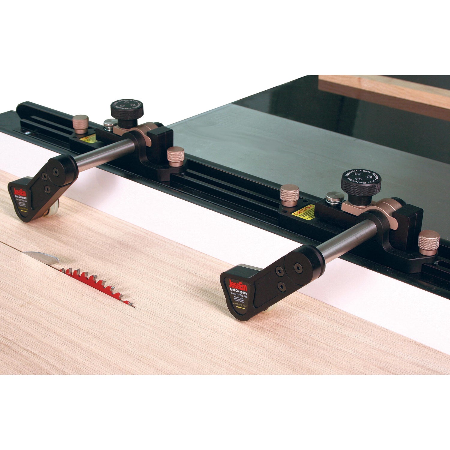
2 Using a quality crosscut blade, cut the top ends of the legs (A) at a 5° angle and bevel (Photo A). To do this, mark the outside or best faces for the left front, left back, right front, and right back legs. Now, adjust the saw blade and miter gauge for the compound cuts. With a left-tilt blade and the miter gauge and extension fence in the left-hand slot, cut two leg top ends with their outside faces up. Without changing the settings, move the miter gauge and extension fence to the other side of the blade, place the remaining two legs outside face down, and cut their top ends. This will result in two sets of front and back legs, or one set for each side. (Follow the same procedure for a right-tilt saw.)
3 With the blade at 90°, cut the 5° angles on the ends of side rails (B), (C), and (D), as shown in Figure 2. Use a stop on the extension fence to ensure that part pairs are cut to identical lengths.
4 Adjust the fence, tilt the blade 5° away from the fence, and bevel-rip the top edge of parts (B) to match the top ends of legs (A).
5 Then, on a flat surface, position rails (B), (C), and (D) between the sets of front and back legs.
Fit the top side rails (B) flush with the top ends of the legs. Fit the other rails below, making sure the joints are snug. They should match the dimensions in the Base Side View in Figure 2.
Mark centered biscuit slot locations on the ends of the rails and corresponding locations on the legs. Mark the centers for the biscuit locations on the front edges of the front legs and back edges of the back legs. Note that the side assemblies (A, B, C, D) require slots for #20 biscuits and that the front and back rails (E, F, G) require slots for #0 biscuits.
Tip Alert
6 Now make the Leg-Slotting Jig and Rail-Slotting Jig shown in Figure 3.
7 Using the leg-slotting jig, cut biscuit slots in the legs’ inside edges and faces. When slotting the faces, gang the two legs together to provide bearing for the biscuit joiner’s fence, as shown in Photo B. Note that edge slots are centered across the legs’ thickness while face slots are 3⁄8" in from the outside edges.
8 Clamp the rail-slotting jig to the bench and position and clamp a rail in place, flush with the edge of the jig. Use a stop to center the joiner’s cutter on the rail’s end and aligned with the cut line. Now make the cut. Keeping the same face up, rotate the rail and move it to the other side of the jig. Repeat the process to cut a slot in the rail’s opposite end (Photo C). Cut slots in the remaining rails.


9 Working off a centerline, lay out the locations for the turned spindles in the side rails, spacing them 11⁄2" apart, as shown in Figure 2. Check the hole diameter for the tenons by making a test hole. Now drill the centered 1⁄4" holes 9⁄16" deep (Photo D).
10 Lay out an arc with a 15" radius on a piece of plywood or MDF. Use it to lay out the arcs on the bottom edges of the bottom side rails (D), where shown in Figure 2, as well as later arcs. Bandsaw the bottom side rails to final shape; sand smooth.
11 Make four Tapered Clamping Cauls like the ones in Figure 3. (I started with two 3⁄4 × 3 3⁄4 × 22" pieces of MDF and taper-cut each piece at 5° on the bandsaw, where shown, to make four tapered wedges. Then I cleaned the sawn edges on the jointer.) To prevent the cauls from slipping in use, screw and glue on small 1⁄4 × 3⁄4 × 2" hardwood cleats on the 1" ends, or stick strips of self-adhesive sandpaper on the cauls’ tapered edges.
12 On a flat surface, position and dry-fit the parts, including the spindles, for one side to assure a proper fit. Now use biscuits to bond the rails to the legs, using glue having a longer open time (Photo E). Remove glue squeeze-out with a clean, moistened rag. Glue up the second side assembly. Set both aside to dry.
13 With the miter gauge extension fence set at 5° and the saw blade tilted 5°, bevel-cut the ends of the side assemblies (Photo F).


With the marks of the rails and one side aligned and glue applied, biscuit-join the parts, using the dry-fit opposite side as a spacer.
Cut more rails and assemble the base
1 Gather up the top, middle, and bottom front and rear rails (E, F, G, respectively) and footrest (H). On the top rails (E), rip a 5° bevel on the upper edge, where shown in Figure 2.
Now trim all of the front and rear rails to final length by angle-cutting the ends at 5°.
2 Mark centerlines on the ends of the rails and biscuit-cut slots for #0 biscuits, using the Rail Slotting Jig.
3 Lay out the arcs on the center rails (F) and bottom rails (G), and cut to shape; sand smooth.
4 Working on a raised surface, place a side assembly (A/B/C/D) face down on top of the Tapered Clamping Cauls. Apply glue to the biscuit slots in the side and to the slots in the mating ends of the top, middle, and bottom front and back rails (E, F, G). Add the biscuits and join the rails to the side. Dry-fit the remaining side to the glue-up, add two more tapered clamping cauls, and clamp, as shown in Photo G.
5 After the glue has dried in one rail and side assembly (A/B/C/D/E/F/G), undo the clamps and remove the dry-fit side. Now, add glue, and biscuit-join the remaining side to the rails, again, using the tapered clamping cauls and clamps for even clamping pressure. Remove any squeeze-out, and check for square.
6 Hold the oversized part for footrest (H) to the legs at its intended location and mark the ends. Bevel-cut the ends at 5°. Now, mark the radius, bandsaw, and sand. Glue and clamp the footrest to the middle front rail (F).


Tip Alert
Make the seat
1 To make the seat (I), edge-glue 3⁄4"-thick pieces to make the overall size. Sand the surface smooth.
2 Lay out and saw the seat (I) to the shape in Figure 4. Sand the edges smooth.
3 Drill and countersink holes on the bottom face of the seat (I), where shown in Figure 4, for #8 × 2" flathead wood screws. These are for attaching the arm and chair back assemblies.

Add the arms
1 Next cut the back supports (J), arm supports (K), and the arms (L) to length with a 10° angle at one end.
2 Lay out, cut, and sand the rounded ends of the back supports (J) and arms (L). See Figure 4.
3 To attach the upper and lower back rails (M, N) to the back supports (J), lay out the biscuit slot locations. Employ the slotting jigs to cut the slots for #0 biscuits.
4 Lay out and then drill the 1⁄4" dowel holes, 13⁄16" deep in the back supports (J), arm supports (K), and arms (L) using a doweling jig (Photo H).
5 Now glue and clamp up the arm assembly parts (J, K, L), as shown in Photo I. After the glue dries, remove clamps and sand smooth.


With the high chair upside down on the bench, use a cordless drill and bit extensions to screw the seat to the base where shown.
Now for the back
1 Crosscut the upper back rail (M) and lower back rail (N) to length.
2 Cut the slots in the ends of the rails (M, N).
3 Lay out and drill the holes for the turned spindles.
4 Lay out the arc on the upper back rail (M). Bandsaw and sand the arc.
5 Dry-fit the back rails (M, N) and spindles to the arm assemblies (J/K/L). Then, apply glue to the slots, assemble the parts with biscuits, and clamp. (I used a little glue in the spindle holes on one rail to prevent rattling.)

Assemble the doll high chair
1 Position the seat back/arm assembly (J/K/L/M/N) upside down on the workbench, centering it from side to side (or 3⁄4" in from the side and back edges of the seat [I]). Clamp it in place. With the holes as guides, drill pilot holes and drive the screws (Photo J).
2 Using a 3⁄4" Forstner bit, slowly drill recesses in the top inside edges of side top rails (B) for four figure-8 tabletop fasteners. I located them 2" in from the outside edge and 1⁄2" in from the outside faces. Test the fit.
You want them a hair deeper than the thickness of the fasteners. Drill a pilot hole, and then screw them in place with #8 × 5⁄8" flathead wood screws. Now, attach the seat/arm/back assembly to the chair base, as shown in Photo K.

Build and add the tray
1 Cut the tray supports (O) and the tray (P) to size plus 1" long. To get the exact width of the tray, measure the width of the back of the chair plus the thickness of two flat washers. Now edge-glue the tray supports to the tray. After the glue dries, scrape and sand the joints.
2 Use the dimensional information in the Figure 5 Tray View to lay out the tray assembly (O/P) on the glue-up. Set the miter gauge extension fence to 0° and angle the blade at 10°. Now bevel-cut the back ends of the tray supports (O) to match the angled back supports (J).
3 Lay out the shank holes for #10 × 2" roundhead screws, 5⁄8" in from the back ends of (O) and centered. Drill the holes at the drill press.
4 Bandsaw the notched areas and the arc along the front edge of the tray assembly (O/P). Sand the edges smooth.
5 To attach the tray assembly (O/P), clamp it to the arms (L), and align it with the back supports (J). Using the shank holes and a small brad-point bit, locate and mark the hole locations on the back supports. Remove the tray assembly, and drill pilot holes for #10 × 2" roundhead screws. Now position the four flat washers, where shown in Figure 1, and drive the screws (Photo L).
Note: If you are concerned about the tray pinching small fingers, consider screwing the tray to the arms from underneath.
6 To finish, remove the tray assembly (O/P), and sand all surfaces to 220 grit, easing all edges. Then apply three coats of water-based polyurethane, sanding between coats. Reassemble.
About Our Designer/Builder
Iowa native Chuck Hedlund worked for years in custom millwork, designing and building furniture and cabinets. In 1993, he began serving the needs of several woodworking magazines as a designer, master craftsman, and shop foreman. In 2008, he retired and moved to Columbus, Ohio, where he freelances as a designer and builder.


